

In this chapter we will focus on the following topics:
- Implementing skeletal animation using matrix palette skinning
- Implementing skeletal animation using dual quaternion skinning
- Modeling cloth using transform feedback
- Implementing collision detection and response on a transform feedback-based cloth model
- Implementing a particle system using transform feedback
Most of the real-time graphics applications have interactive elements. We have automated bots that move and animate in an interactive application. These elements include objects that are animated using preset sequences of frames. These are called frame-by-frame animations. There are other scene elements that have motion, which is derived using physical simulation. These are called physically-based animations. In addition, humanoid or character models have a special category of animations called skeletal animation. In this chapter, we will look at recipes for doing skeletal and physically-based simulation on the GPU in modern OpenGL.
When working with games and simulation systems, virtual characters are often used to give a detailed depiction of scenarios. Such characters are typically represented using a combination of bones and skin. The vertices of the 3D model are assigned influence weights (called blend weights) that control how much a bone influences that vertex. Up to four bones can influence a vertex. The process whereby bone weights are assigned to the vertices of a 3D model is called skinning. Each bone stores its transformation. These stored sequences of transformations are applied to every frame and every bone in the model and in the end, we get an animated character on the screen. This representation of animation is called skeletal animation. There are several methods for skeletal animation. One popular method is matrix palette skinning, which is also known as linear blend skinning (LBS). This method will be implemented in this recipe.
The code for this recipe is contained in the Chapter8/MatrixPaletteSkinning directory. This recipe will be using the Implementing EZMesh model loading recipe from Chapter 5, Mesh Model Formats and Particle Systems and it will augment it with skeletal animation. The EZMesh format was developed by John Ratcliff and it is an easy-to-understand format for storing skeletal animation. Typical skeletal animation formats like COLLADA and FBX are needlessly complicated, where dozens of segments have to be parsed before the real content can be loaded. On the other hand, the EZMesh format stores all of the information in an XML-based format, which is easier to parse. It is the default skeletal animation format used in the NVIDIA PhysX sdk. More information about the EZMesh model format and loaders can be obtained from the references in the See also section of this recipe.
Let us start our recipe by following these simple steps:
- Load the EZMesh model as we did in the Implementing EZMesh loader recipe from Chapter 5, Mesh Model Formats and Particle System. In addition to the model submeshes, vertices, normals, texture coordinates, and materials, we also load the skeleton information from the EZMesh file.
EzmLoader ezm; if(!ezm.Load(mesh_filename.c_str(), skeleton, animations, submeshes, vertices, indices, material2ImageMap, min, max)) { cout<<"Cannot load the EZMesh file"<<endl; exit(EXIT_FAILURE); }
- Get the
MeshSystemobject from themeshImportLibraryobject. Then load the bone transformations contained in the EZMesh file using theMeshSystem::mSkeletonsarray. This is carried out in theEzmLoader::Loadfunction. Also generate absolute bone transforms from the relative transforms. This is done so that the transform of the child bone is influenced by the transform of the parent bone. This is continued up the hierarchy until the root bone. If the mesh is modeled in a positive Z axis system, we need to modify the orientation, positions, and scale by swapping Y and Z axes and changing the sign of one of them. This is done because we are using a positive Y axis system in OpenGL; otherwise, our mesh will be lying in the XZ plane rather than the XY plane. We obtain a combined matrix from the position orientation and scale of the bone. This is stored in thexformfield, which is the relative transform of the bone.if(ms->mSkeletonCount>0) { NVSHARE::MeshSkeleton* pSkel = ms->mSkeletons[0]; Bone b; for(int i=0;i<pSkel->GetBoneCount();i++) { const NVSHARE::MeshBone pBone = pSkel->mBones[i]; const int s = strlen(pBone.mName); b.name = new char[s+1]; memset(b.name, 0, sizeof(char)*(s+1)); strncpy_s(b.name,sizeof(char)*(s+1), pBone.mName, s); b.orientation = glm::quat( pBone.mOrientation[3],pBone.mOrientation[0], pBone.mOrientation[1],pBone.mOrientation[2]); b.position = glm::vec3( pBone.mPosition[0], pBone.mPosition[1],pBone.mPosition[2]); b.scale = glm::vec3(pBone.mScale[0], pBone.mScale[1], pBone.mScale[2]); if(!bYup) { float tmp = b.position.y; b.position.y = b.position.z; b.position.z = -tmp; tmp = b.orientation.y; b.orientation.y = b.orientation.z; b.orientation.z = -tmp; tmp = b.scale.y; b.scale.y = b.scale.z; b.scale.z = -tmp; } glm::mat4 S = glm::scale(glm::mat4(1), b.scale); glm::mat4 R = glm::toMat4(b.orientation); glm::mat4 T = glm::translate(glm::mat4(1), b.position); b.xform = T*R*S; b.parent = pBone.mParentIndex; skeleton.push_back(b); } UpdateCombinedMatrices(); bindPose.resize(skeleton.size()); invBindPose.resize(skeleton.size()); animatedXform.resize(skeleton.size()); - Generate the bind pose and inverse bind pose arrays from the stored bone transformations:
for(size_t i=0;i<skeleton.size();i++) { bindPose[i] = (skeleton[i].comb); invBindPose[i] = glm::inverse(bindPose[i]); }} - Store the blend weights and blend indices of each vertex in the mesh:
mesh.vertices[j].blendWeights.x = pMesh->mVertices[j].mWeight[0]; mesh.vertices[j].blendWeights.y = pMesh->mVertices[j].mWeight[1]; mesh.vertices[j].blendWeights.z = pMesh->mVertices[j].mWeight[2]; mesh.vertices[j].blendWeights.w = pMesh->mVertices[j].mWeight[3]; mesh.vertices[j].blendIndices[0] = pMesh->mVertices[j].mBone[0]; mesh.vertices[j].blendIndices[1] = pMesh->mVertices[j].mBone[1]; mesh.vertices[j].blendIndices[2] = pMesh->mVertices[j].mBone[2]; mesh.vertices[j].blendIndices[3] = pMesh->mVertices[j].mBone[3];
- In the idle callback function, calculate the amount of time to spend on the current frame. If the amount has elapsed, move to the next frame and reset the time. After this, calculate the new bone transformations as well as new skinning matrices, and pass them to the shader:
QueryPerformanceCounter(¤t); dt = (double)(current.QuadPart - last.QuadPart) / (double)freq.QuadPart; last = current; static double t = 0; t+=dt; NVSHARE::MeshAnimation* pAnim = &animations[0]; float framesPerSecond = pAnim->GetFrameCount()/ pAnim->GetDuration(); if( t > 1.0f/ framesPerSecond) { currentFrame++; t=0; } if(bLoop) { currentFrame = currentFrame%pAnim->mFrameCount; } else { currentFrame=max(-1,min(currentFrame,pAnim->mFrameCount-1)); } if(currentFrame == -1) { for(size_t i=0;i<skeleton.size();i++) { skeleton[i].comb = bindPose[i]; animatedXform[i] = skeleton[i].comb*invBindPose[i]; } } else { for(int j=0;j<pAnim->mTrackCount;j++) { NVSHARE::MeshAnimTrack* pTrack = pAnim->mTracks[j]; NVSHARE::MeshAnimPose* pPose = pTrack->GetPose(currentFrame); skeleton[j].position.x = pPose->mPos[0]; skeleton[j].position.y = pPose->mPos[1]; skeleton[j].position.z = pPose->mPos[2]; glm::quat q; q.x = pPose->mQuat[0]; q.y = pPose->mQuat[1]; q.z = pPose->mQuat[2]; q.w = pPose->mQuat[3]; skeleton[j].scale = glm::vec3(pPose->mScale[0], pPose->mScale[1], pPose->mScale[2]); if(!bYup) { skeleton[j].position.y = pPose->mPos[2]; skeleton[j].position.z = -pPose->mPos[1]; q.y = pPose->mQuat[2]; q.z = -pPose->mQuat[1]; skeleton[j].scale.y = pPose->mScale[2]; skeleton[j].scale.z = -pPose->mScale[1]; } skeleton[j].orientation = q; glm::mat4 S =glm::scale(glm::mat4(1),skeleton[j].scale); glm::mat4 R = glm::toMat4(q); glm::mat4 T = glm::translate(glm::mat4(1), skeleton[j].position); skeleton[j].xform = T*R*S; Bone& b = skeleton[j]; if(b.parent==-1) b.comb = b.xform; else b.comb = skeleton[b.parent].comb * b.xform; animatedXform[j] = b.comb * invBindPose[j] ; } } shader.Use(); glUniformMatrix4fv(shader("Bones"),animatedXform.size(), GL_FALSE,glm::value_ptr(animatedXform[0])); shader.UnUse(); shader.UnUse();
There are two parts of this recipe: generation of skinning matrices and the calculation of GPU skinning in the vertex shader. To understand the first step, we will start with the different transforms that will be used in skinning. Typically, in a simulation or game, a transform is represented as a 4×4 matrix. For skeletal animation, we have a collection of bones. Each bone has a local transform (also called relative transform), which tells how the bone is positioned and oriented with respect to its parent bone. If the bone's local transform is multiplied to the global transform of its parent, we get the global transform (also called absolute transform) of the bone. Typically, the animation formats store the local transforms of the bones in the file. The user application uses this information to generate the global transforms.
We define our bone structure as follows:
The first field is orientation, which is a quaternion storing the orientation of bone in space relative to its parent. The position field stores its position relative to its parent. The xform field is the local (relative) transform, and the comb field is the global (absolute) transform. The scale field contains the scaling transformation of the bone. In the big picture, the scale field gives the scaling matrix (S), the orientation field gives the rotation matrix (R), and the position field gives the translation matrix (T). The combined matrix T*R*S gives us the relative transform that is calculated when we load the bone information from the EZMesh file in the second step.
Note that we do this once at initialization, so that we do not have to calculate the bind pose's inverse every frame, as it is required during animation.
The final matrix that we get from this process is called the skinning matrix (also called the final bone matrix). Continuing from the example given in the previous paragraph, let's say we have modified the relative transforms of bone using the animation sequence. We can then generate the skinning matrix as follows:
After we have calculated the skinning matrices, we pass these to the GPU in a single call:
This ensures that our vertex shader has the same number of bones as our mesh file.
The Vertex struct storing all of our per-vertex attributes is defined as follows:
Finally, in the rendering code, we set the vertex array object and use the shader program. Then we iterate through all of the submeshes. We then set the material texture for the current submesh and set the shader uniforms. Finally, we issue a glDrawElements call:
The matrix palette skinning is carried out on the GPU using the vertex shader (Chapter8/MatrixPaletteSkinning/shaders/shader.vert). We simply use the blend indices and blend weights to calculate the correct vertex position and normal based on the combined influence of all of the effecting bones. The Bones array contains the skinning matrices that we generated earlier. The complete vertex shader is as follows:
The fragment shader uses the attenuated point light source for illumination as we have seen in the Implementing per-fragment point light with attenuation recipe in Chapter 4, Lights and Shadows.
- NVIDIA DirectX SDK 9.0 Matrix Palette Skinning demo at http://http.download.nvidia.com/developer/SDK/Individual_Samples/DEMOS/Direct3D9/src/HLSL_PaletteSkin/docs/HLSL_PaletteSkin.pdf
- John Ratcliff code suppository containing a lot of useful tools, including the EZMesh format specifications and loaders available online at http://codesuppository.blogspot.sg/2009/11/test-application-for-meshimport-library.html
- Improved Skinning demo in the NVIDIA sdk at http://http.download.nvidia.com/developer/SDK/Individual_Samples/samples.html
Chapter8/MatrixPaletteSkinning directory. This recipe will be using the Implementing EZMesh model loading recipe from
Chapter 5, Mesh Model Formats and Particle Systems and it will augment it with skeletal animation. The EZMesh format was developed by John Ratcliff and it is an easy-to-understand format for storing skeletal animation. Typical skeletal animation formats like COLLADA and FBX are needlessly complicated, where dozens of segments have to be parsed before the real content can be loaded. On the other hand, the EZMesh format stores all of the information in an XML-based format, which is easier to parse. It is the default skeletal animation format used in the NVIDIA PhysX sdk. More information about the EZMesh model format and loaders can be obtained from the references in the See also section of this recipe.
Let us start our recipe by following these simple steps:
- Load the EZMesh model as we did in the Implementing EZMesh loader recipe from Chapter 5, Mesh Model Formats and Particle System. In addition to the model submeshes, vertices, normals, texture coordinates, and materials, we also load the skeleton information from the EZMesh file.
EzmLoader ezm; if(!ezm.Load(mesh_filename.c_str(), skeleton, animations, submeshes, vertices, indices, material2ImageMap, min, max)) { cout<<"Cannot load the EZMesh file"<<endl; exit(EXIT_FAILURE); }
- Get the
MeshSystemobject from themeshImportLibraryobject. Then load the bone transformations contained in the EZMesh file using theMeshSystem::mSkeletonsarray. This is carried out in theEzmLoader::Loadfunction. Also generate absolute bone transforms from the relative transforms. This is done so that the transform of the child bone is influenced by the transform of the parent bone. This is continued up the hierarchy until the root bone. If the mesh is modeled in a positive Z axis system, we need to modify the orientation, positions, and scale by swapping Y and Z axes and changing the sign of one of them. This is done because we are using a positive Y axis system in OpenGL; otherwise, our mesh will be lying in the XZ plane rather than the XY plane. We obtain a combined matrix from the position orientation and scale of the bone. This is stored in thexformfield, which is the relative transform of the bone.if(ms->mSkeletonCount>0) { NVSHARE::MeshSkeleton* pSkel = ms->mSkeletons[0]; Bone b; for(int i=0;i<pSkel->GetBoneCount();i++) { const NVSHARE::MeshBone pBone = pSkel->mBones[i]; const int s = strlen(pBone.mName); b.name = new char[s+1]; memset(b.name, 0, sizeof(char)*(s+1)); strncpy_s(b.name,sizeof(char)*(s+1), pBone.mName, s); b.orientation = glm::quat( pBone.mOrientation[3],pBone.mOrientation[0], pBone.mOrientation[1],pBone.mOrientation[2]); b.position = glm::vec3( pBone.mPosition[0], pBone.mPosition[1],pBone.mPosition[2]); b.scale = glm::vec3(pBone.mScale[0], pBone.mScale[1], pBone.mScale[2]); if(!bYup) { float tmp = b.position.y; b.position.y = b.position.z; b.position.z = -tmp; tmp = b.orientation.y; b.orientation.y = b.orientation.z; b.orientation.z = -tmp; tmp = b.scale.y; b.scale.y = b.scale.z; b.scale.z = -tmp; } glm::mat4 S = glm::scale(glm::mat4(1), b.scale); glm::mat4 R = glm::toMat4(b.orientation); glm::mat4 T = glm::translate(glm::mat4(1), b.position); b.xform = T*R*S; b.parent = pBone.mParentIndex; skeleton.push_back(b); } UpdateCombinedMatrices(); bindPose.resize(skeleton.size()); invBindPose.resize(skeleton.size()); animatedXform.resize(skeleton.size()); - Generate the bind pose and inverse bind pose arrays from the stored bone transformations:
for(size_t i=0;i<skeleton.size();i++) { bindPose[i] = (skeleton[i].comb); invBindPose[i] = glm::inverse(bindPose[i]); }} - Store the blend weights and blend indices of each vertex in the mesh:
mesh.vertices[j].blendWeights.x = pMesh->mVertices[j].mWeight[0]; mesh.vertices[j].blendWeights.y = pMesh->mVertices[j].mWeight[1]; mesh.vertices[j].blendWeights.z = pMesh->mVertices[j].mWeight[2]; mesh.vertices[j].blendWeights.w = pMesh->mVertices[j].mWeight[3]; mesh.vertices[j].blendIndices[0] = pMesh->mVertices[j].mBone[0]; mesh.vertices[j].blendIndices[1] = pMesh->mVertices[j].mBone[1]; mesh.vertices[j].blendIndices[2] = pMesh->mVertices[j].mBone[2]; mesh.vertices[j].blendIndices[3] = pMesh->mVertices[j].mBone[3];
- In the idle callback function, calculate the amount of time to spend on the current frame. If the amount has elapsed, move to the next frame and reset the time. After this, calculate the new bone transformations as well as new skinning matrices, and pass them to the shader:
QueryPerformanceCounter(¤t); dt = (double)(current.QuadPart - last.QuadPart) / (double)freq.QuadPart; last = current; static double t = 0; t+=dt; NVSHARE::MeshAnimation* pAnim = &animations[0]; float framesPerSecond = pAnim->GetFrameCount()/ pAnim->GetDuration(); if( t > 1.0f/ framesPerSecond) { currentFrame++; t=0; } if(bLoop) { currentFrame = currentFrame%pAnim->mFrameCount; } else { currentFrame=max(-1,min(currentFrame,pAnim->mFrameCount-1)); } if(currentFrame == -1) { for(size_t i=0;i<skeleton.size();i++) { skeleton[i].comb = bindPose[i]; animatedXform[i] = skeleton[i].comb*invBindPose[i]; } } else { for(int j=0;j<pAnim->mTrackCount;j++) { NVSHARE::MeshAnimTrack* pTrack = pAnim->mTracks[j]; NVSHARE::MeshAnimPose* pPose = pTrack->GetPose(currentFrame); skeleton[j].position.x = pPose->mPos[0]; skeleton[j].position.y = pPose->mPos[1]; skeleton[j].position.z = pPose->mPos[2]; glm::quat q; q.x = pPose->mQuat[0]; q.y = pPose->mQuat[1]; q.z = pPose->mQuat[2]; q.w = pPose->mQuat[3]; skeleton[j].scale = glm::vec3(pPose->mScale[0], pPose->mScale[1], pPose->mScale[2]); if(!bYup) { skeleton[j].position.y = pPose->mPos[2]; skeleton[j].position.z = -pPose->mPos[1]; q.y = pPose->mQuat[2]; q.z = -pPose->mQuat[1]; skeleton[j].scale.y = pPose->mScale[2]; skeleton[j].scale.z = -pPose->mScale[1]; } skeleton[j].orientation = q; glm::mat4 S =glm::scale(glm::mat4(1),skeleton[j].scale); glm::mat4 R = glm::toMat4(q); glm::mat4 T = glm::translate(glm::mat4(1), skeleton[j].position); skeleton[j].xform = T*R*S; Bone& b = skeleton[j]; if(b.parent==-1) b.comb = b.xform; else b.comb = skeleton[b.parent].comb * b.xform; animatedXform[j] = b.comb * invBindPose[j] ; } } shader.Use(); glUniformMatrix4fv(shader("Bones"),animatedXform.size(), GL_FALSE,glm::value_ptr(animatedXform[0])); shader.UnUse(); shader.UnUse();
There are two parts of this recipe: generation of skinning matrices and the calculation of GPU skinning in the vertex shader. To understand the first step, we will start with the different transforms that will be used in skinning. Typically, in a simulation or game, a transform is represented as a 4×4 matrix. For skeletal animation, we have a collection of bones. Each bone has a local transform (also called relative transform), which tells how the bone is positioned and oriented with respect to its parent bone. If the bone's local transform is multiplied to the global transform of its parent, we get the global transform (also called absolute transform) of the bone. Typically, the animation formats store the local transforms of the bones in the file. The user application uses this information to generate the global transforms.
We define our bone structure as follows:
The first field is orientation, which is a quaternion storing the orientation of bone in space relative to its parent. The position field stores its position relative to its parent. The xform field is the local (relative) transform, and the comb field is the global (absolute) transform. The scale field contains the scaling transformation of the bone. In the big picture, the scale field gives the scaling matrix (S), the orientation field gives the rotation matrix (R), and the position field gives the translation matrix (T). The combined matrix T*R*S gives us the relative transform that is calculated when we load the bone information from the EZMesh file in the second step.
Note that we do this once at initialization, so that we do not have to calculate the bind pose's inverse every frame, as it is required during animation.
The final matrix that we get from this process is called the skinning matrix (also called the final bone matrix). Continuing from the example given in the previous paragraph, let's say we have modified the relative transforms of bone using the animation sequence. We can then generate the skinning matrix as follows:
After we have calculated the skinning matrices, we pass these to the GPU in a single call:
This ensures that our vertex shader has the same number of bones as our mesh file.
The Vertex struct storing all of our per-vertex attributes is defined as follows:
Finally, in the rendering code, we set the vertex array object and use the shader program. Then we iterate through all of the submeshes. We then set the material texture for the current submesh and set the shader uniforms. Finally, we issue a glDrawElements call:
The matrix palette skinning is carried out on the GPU using the vertex shader (Chapter8/MatrixPaletteSkinning/shaders/shader.vert). We simply use the blend indices and blend weights to calculate the correct vertex position and normal based on the combined influence of all of the effecting bones. The Bones array contains the skinning matrices that we generated earlier. The complete vertex shader is as follows:
The fragment shader uses the attenuated point light source for illumination as we have seen in the Implementing per-fragment point light with attenuation recipe in Chapter 4, Lights and Shadows.
- NVIDIA DirectX SDK 9.0 Matrix Palette Skinning demo at http://http.download.nvidia.com/developer/SDK/Individual_Samples/DEMOS/Direct3D9/src/HLSL_PaletteSkin/docs/HLSL_PaletteSkin.pdf
- John Ratcliff code suppository containing a lot of useful tools, including the EZMesh format specifications and loaders available online at http://codesuppository.blogspot.sg/2009/11/test-application-for-meshimport-library.html
- Improved Skinning demo in the NVIDIA sdk at http://http.download.nvidia.com/developer/SDK/Individual_Samples/samples.html
- Chapter 5, Mesh Model Formats and Particle System. In addition to the model submeshes, vertices, normals, texture coordinates, and materials, we also load the skeleton information from the EZMesh file.
EzmLoader ezm; if(!ezm.Load(mesh_filename.c_str(), skeleton, animations, submeshes, vertices, indices, material2ImageMap, min, max)) { cout<<"Cannot load the EZMesh file"<<endl; exit(EXIT_FAILURE); }
- Get the
MeshSystemobject from themeshImportLibraryobject. Then load the bone transformations contained in the EZMesh file using theMeshSystem::mSkeletonsarray. This is carried out in theEzmLoader::Loadfunction. Also generate absolute bone transforms from the relative transforms. This is done so that the transform of the child bone is influenced by the transform of the parent bone. This is continued up the hierarchy until the root bone. If the mesh is modeled in a positive Z axis system, we need to modify the orientation, positions, and scale by swapping Y and Z axes and changing the sign of one of them. This is done because we are using a positive Y axis system in OpenGL; otherwise, our mesh will be lying in the XZ plane rather than the XY plane. We obtain a combined matrix from the position orientation and scale of the bone. This is stored in thexformfield, which is the relative transform of the bone.if(ms->mSkeletonCount>0) { NVSHARE::MeshSkeleton* pSkel = ms->mSkeletons[0]; Bone b; for(int i=0;i<pSkel->GetBoneCount();i++) { const NVSHARE::MeshBone pBone = pSkel->mBones[i]; const int s = strlen(pBone.mName); b.name = new char[s+1]; memset(b.name, 0, sizeof(char)*(s+1)); strncpy_s(b.name,sizeof(char)*(s+1), pBone.mName, s); b.orientation = glm::quat( pBone.mOrientation[3],pBone.mOrientation[0], pBone.mOrientation[1],pBone.mOrientation[2]); b.position = glm::vec3( pBone.mPosition[0], pBone.mPosition[1],pBone.mPosition[2]); b.scale = glm::vec3(pBone.mScale[0], pBone.mScale[1], pBone.mScale[2]); if(!bYup) { float tmp = b.position.y; b.position.y = b.position.z; b.position.z = -tmp; tmp = b.orientation.y; b.orientation.y = b.orientation.z; b.orientation.z = -tmp; tmp = b.scale.y; b.scale.y = b.scale.z; b.scale.z = -tmp; } glm::mat4 S = glm::scale(glm::mat4(1), b.scale); glm::mat4 R = glm::toMat4(b.orientation); glm::mat4 T = glm::translate(glm::mat4(1), b.position); b.xform = T*R*S; b.parent = pBone.mParentIndex; skeleton.push_back(b); } UpdateCombinedMatrices(); bindPose.resize(skeleton.size()); invBindPose.resize(skeleton.size()); animatedXform.resize(skeleton.size()); - Generate the bind pose and inverse bind pose arrays from the stored bone transformations:
for(size_t i=0;i<skeleton.size();i++) { bindPose[i] = (skeleton[i].comb); invBindPose[i] = glm::inverse(bindPose[i]); }} - Store the blend weights and blend indices of each vertex in the mesh:
mesh.vertices[j].blendWeights.x = pMesh->mVertices[j].mWeight[0]; mesh.vertices[j].blendWeights.y = pMesh->mVertices[j].mWeight[1]; mesh.vertices[j].blendWeights.z = pMesh->mVertices[j].mWeight[2]; mesh.vertices[j].blendWeights.w = pMesh->mVertices[j].mWeight[3]; mesh.vertices[j].blendIndices[0] = pMesh->mVertices[j].mBone[0]; mesh.vertices[j].blendIndices[1] = pMesh->mVertices[j].mBone[1]; mesh.vertices[j].blendIndices[2] = pMesh->mVertices[j].mBone[2]; mesh.vertices[j].blendIndices[3] = pMesh->mVertices[j].mBone[3];
- In the idle callback function, calculate the amount of time to spend on the current frame. If the amount has elapsed, move to the next frame and reset the time. After this, calculate the new bone transformations as well as new skinning matrices, and pass them to the shader:
QueryPerformanceCounter(¤t); dt = (double)(current.QuadPart - last.QuadPart) / (double)freq.QuadPart; last = current; static double t = 0; t+=dt; NVSHARE::MeshAnimation* pAnim = &animations[0]; float framesPerSecond = pAnim->GetFrameCount()/ pAnim->GetDuration(); if( t > 1.0f/ framesPerSecond) { currentFrame++; t=0; } if(bLoop) { currentFrame = currentFrame%pAnim->mFrameCount; } else { currentFrame=max(-1,min(currentFrame,pAnim->mFrameCount-1)); } if(currentFrame == -1) { for(size_t i=0;i<skeleton.size();i++) { skeleton[i].comb = bindPose[i]; animatedXform[i] = skeleton[i].comb*invBindPose[i]; } } else { for(int j=0;j<pAnim->mTrackCount;j++) { NVSHARE::MeshAnimTrack* pTrack = pAnim->mTracks[j]; NVSHARE::MeshAnimPose* pPose = pTrack->GetPose(currentFrame); skeleton[j].position.x = pPose->mPos[0]; skeleton[j].position.y = pPose->mPos[1]; skeleton[j].position.z = pPose->mPos[2]; glm::quat q; q.x = pPose->mQuat[0]; q.y = pPose->mQuat[1]; q.z = pPose->mQuat[2]; q.w = pPose->mQuat[3]; skeleton[j].scale = glm::vec3(pPose->mScale[0], pPose->mScale[1], pPose->mScale[2]); if(!bYup) { skeleton[j].position.y = pPose->mPos[2]; skeleton[j].position.z = -pPose->mPos[1]; q.y = pPose->mQuat[2]; q.z = -pPose->mQuat[1]; skeleton[j].scale.y = pPose->mScale[2]; skeleton[j].scale.z = -pPose->mScale[1]; } skeleton[j].orientation = q; glm::mat4 S =glm::scale(glm::mat4(1),skeleton[j].scale); glm::mat4 R = glm::toMat4(q); glm::mat4 T = glm::translate(glm::mat4(1), skeleton[j].position); skeleton[j].xform = T*R*S; Bone& b = skeleton[j]; if(b.parent==-1) b.comb = b.xform; else b.comb = skeleton[b.parent].comb * b.xform; animatedXform[j] = b.comb * invBindPose[j] ; } } shader.Use(); glUniformMatrix4fv(shader("Bones"),animatedXform.size(), GL_FALSE,glm::value_ptr(animatedXform[0])); shader.UnUse(); shader.UnUse();
There are two parts of this recipe: generation of skinning matrices and the calculation of GPU skinning in the vertex shader. To understand the first step, we will start with the different transforms that will be used in skinning. Typically, in a simulation or game, a transform is represented as a 4×4 matrix. For skeletal animation, we have a collection of bones. Each bone has a local transform (also called relative transform), which tells how the bone is positioned and oriented with respect to its parent bone. If the bone's local transform is multiplied to the global transform of its parent, we get the global transform (also called absolute transform) of the bone. Typically, the animation formats store the local transforms of the bones in the file. The user application uses this information to generate the global transforms.
We define our bone structure as follows:
The first field is orientation, which is a quaternion storing the orientation of bone in space relative to its parent. The position field stores its position relative to its parent. The xform field is the local (relative) transform, and the comb field is the global (absolute) transform. The scale field contains the scaling transformation of the bone. In the big picture, the scale field gives the scaling matrix (S), the orientation field gives the rotation matrix (R), and the position field gives the translation matrix (T). The combined matrix T*R*S gives us the relative transform that is calculated when we load the bone information from the EZMesh file in the second step.
Note that we do this once at initialization, so that we do not have to calculate the bind pose's inverse every frame, as it is required during animation.
The final matrix that we get from this process is called the skinning matrix (also called the final bone matrix). Continuing from the example given in the previous paragraph, let's say we have modified the relative transforms of bone using the animation sequence. We can then generate the skinning matrix as follows:
After we have calculated the skinning matrices, we pass these to the GPU in a single call:
This ensures that our vertex shader has the same number of bones as our mesh file.
The Vertex struct storing all of our per-vertex attributes is defined as follows:
Finally, in the rendering code, we set the vertex array object and use the shader program. Then we iterate through all of the submeshes. We then set the material texture for the current submesh and set the shader uniforms. Finally, we issue a glDrawElements call:
The matrix palette skinning is carried out on the GPU using the vertex shader (Chapter8/MatrixPaletteSkinning/shaders/shader.vert). We simply use the blend indices and blend weights to calculate the correct vertex position and normal based on the combined influence of all of the effecting bones. The Bones array contains the skinning matrices that we generated earlier. The complete vertex shader is as follows:
The fragment shader uses the attenuated point light source for illumination as we have seen in the Implementing per-fragment point light with attenuation recipe in Chapter 4, Lights and Shadows.
- NVIDIA DirectX SDK 9.0 Matrix Palette Skinning demo at http://http.download.nvidia.com/developer/SDK/Individual_Samples/DEMOS/Direct3D9/src/HLSL_PaletteSkin/docs/HLSL_PaletteSkin.pdf
- John Ratcliff code suppository containing a lot of useful tools, including the EZMesh format specifications and loaders available online at http://codesuppository.blogspot.sg/2009/11/test-application-for-meshimport-library.html
- Improved Skinning demo in the NVIDIA sdk at http://http.download.nvidia.com/developer/SDK/Individual_Samples/samples.html
parts of this recipe: generation of skinning matrices and the calculation of GPU skinning in the vertex shader. To understand the first step, we will start with the different transforms that will be used in skinning. Typically, in a simulation or game, a transform is represented as a 4×4 matrix. For skeletal animation, we have a collection of bones. Each bone has a local transform (also called relative transform), which tells how the bone is positioned and oriented with respect to its parent bone. If the bone's local transform is multiplied to the global transform of its parent, we get the global transform (also called absolute transform) of the bone. Typically, the animation formats store the local transforms of the bones in the file. The user application uses this information to generate the global transforms.
We define our bone structure as follows:
The first field is orientation, which is a quaternion storing the orientation of bone in space relative to its parent. The position field stores its position relative to its parent. The xform field is the local (relative) transform, and the comb field is the global (absolute) transform. The scale field contains the scaling transformation of the bone. In the big picture, the scale field gives the scaling matrix (S), the orientation field gives the rotation matrix (R), and the position field gives the translation matrix (T). The combined matrix T*R*S gives us the relative transform that is calculated when we load the bone information from the EZMesh file in the second step.
Note that we do this once at initialization, so that we do not have to calculate the bind pose's inverse every frame, as it is required during animation.
The final matrix that we get from this process is called the skinning matrix (also called the final bone matrix). Continuing from the example given in the previous paragraph, let's say we have modified the relative transforms of bone using the animation sequence. We can then generate the skinning matrix as follows:
After we have calculated the skinning matrices, we pass these to the GPU in a single call:
This ensures that our vertex shader has the same number of bones as our mesh file.
The Vertex struct storing all of our per-vertex attributes is defined as follows:
Finally, in the rendering code, we set the vertex array object and use the shader program. Then we iterate through all of the submeshes. We then set the material texture for the current submesh and set the shader uniforms. Finally, we issue a glDrawElements call:
The matrix palette skinning is carried out on the GPU using the vertex shader (Chapter8/MatrixPaletteSkinning/shaders/shader.vert). We simply use the blend indices and blend weights to calculate the correct vertex position and normal based on the combined influence of all of the effecting bones. The Bones array contains the skinning matrices that we generated earlier. The complete vertex shader is as follows:
The fragment shader uses the attenuated point light source for illumination as we have seen in the Implementing per-fragment point light with attenuation recipe in Chapter 4, Lights and Shadows.
- NVIDIA DirectX SDK 9.0 Matrix Palette Skinning demo at http://http.download.nvidia.com/developer/SDK/Individual_Samples/DEMOS/Direct3D9/src/HLSL_PaletteSkin/docs/HLSL_PaletteSkin.pdf
- John Ratcliff code suppository containing a lot of useful tools, including the EZMesh format specifications and loaders available online at http://codesuppository.blogspot.sg/2009/11/test-application-for-meshimport-library.html
- Improved Skinning demo in the NVIDIA sdk at http://http.download.nvidia.com/developer/SDK/Individual_Samples/samples.html
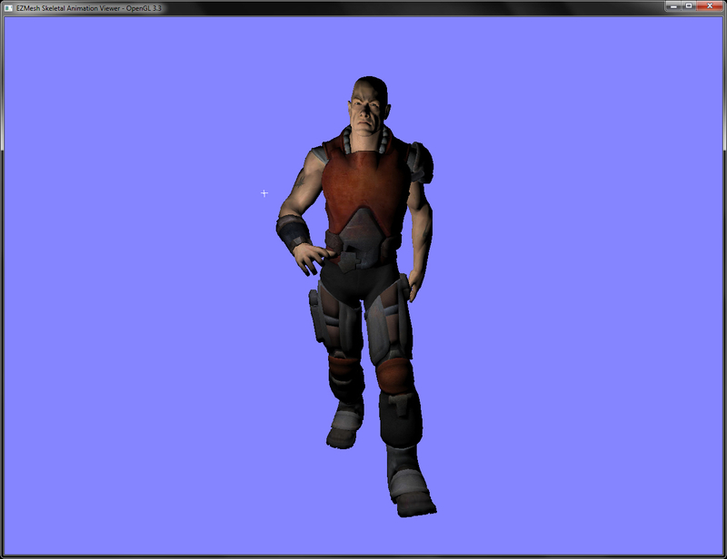
dude.ezm model animating using the matrix palette skinning technique as shown in the following figure. The light source can be rotated by right-clicking on it and dragging. Pressing the l key stops the loop playback.
- NVIDIA DirectX SDK 9.0 Matrix Palette Skinning demo at http://http.download.nvidia.com/developer/SDK/Individual_Samples/DEMOS/Direct3D9/src/HLSL_PaletteSkin/docs/HLSL_PaletteSkin.pdf
- John Ratcliff code suppository containing a lot of useful tools, including the EZMesh format specifications and loaders available online at http://codesuppository.blogspot.sg/2009/11/test-application-for-meshimport-library.html
- Improved Skinning demo in the NVIDIA sdk at http://http.download.nvidia.com/developer/SDK/Individual_Samples/samples.html
- http://http.download.nvidia.com/developer/SDK/Individual_Samples/DEMOS/Direct3D9/src/HLSL_PaletteSkin/docs/HLSL_PaletteSkin.pdf
- John Ratcliff code suppository containing a lot of useful tools, including the EZMesh format specifications and loaders available online at http://codesuppository.blogspot.sg/2009/11/test-application-for-meshimport-library.html
- Improved Skinning demo in the NVIDIA sdk at http://http.download.nvidia.com/developer/SDK/Individual_Samples/samples.html
Matrix palette skinning suffers from candy wrapping artefacts, especially in regions like shoulder and elbow, where there are several rotations across various axes. If dual quaternion skinning is employed, these artefacts are minimized. In this recipe we will implement skeletal animation using dual quaternion skinning.
Before understanding dual quaternions, let us first see what quaternions are. Quaternions are a mathematical entity containing three imaginary dimensions (which specify the axis of rotation) and a real dimension (which specifies the angle of rotation). Quaternions are used in 3D graphics to represent rotation, since they do not suffer from gimbal lock, as Euler angles do. In order to store translation with rotation simultaneously, dual quaternions are used to store dual number coefficients instead of real ones. Instead of four components, as in a quaternion, dual quaternions have eight components.
Even in dual quaternion skinning, the linear blend method is used. However, due to the nature of transformation in dual quaternion, spherical blending is preferred. After linear blending, the resulting dual quaternion is renormalized, which generates a spherical blending result, which is a better approximation as compared to the linear blend skinning. This whole process is illustrated by the following figure:

Converting linear blend skinning to dual quaternion skinning requires the following steps:
- Load the EZMesh model as we did in the Implementing EZMesh loader recipe from Chapter 5, Mesh Model Formats and Particle System:
if(!ezm.Load(mesh_filename.c_str(), skeleton, animations, submeshes, vertices, indices, material2ImageMap, min, max)) { cout<<"Cannot load the EZMesh file"<<endl; exit(EXIT_FAILURE); } - After loading up the mesh, materials, and textures, load the bone transformations contained in the EZMesh file using the
MeshSystem::mSkeletonsarray as we did in the previous recipe. In addition to the bone matrices, also store the bind pose and inverse bind pose matrices as we did in the previous recipe. Instead of storing the skinning matrices, we initialize a vector of dual quaternions. Dual quaternions are a different representation of the skinning matrices.UpdateCombinedMatrices(); bindPose.resize(skeleton.size()); invBindPose.resize(skeleton.size()); animatedXform.resize(skeleton.size()); dualQuaternions.resize(skeleton.size()); for(size_t i=0;i<skeleton.size();i++) { bindPose[i] = (skeleton[i].comb); invBindPose[i] = glm::inverse(bindPose[i]); } - Implement the idle callback function as in the previous recipe. Here, in addition to calculating the skinning matrix, also calculate the dual quaternion for the given skinning matrix. After all of the joints are done, pass the dual quaternion to the shader:
glm::mat4 S = glm::scale(glm::mat4(1),skeleton[j].scale); glm::mat4 R = glm::toMat4(q); glm::mat4 T = glm::translate(glm::mat4(1), skeleton[j].position); skeleton[j].xform = T*R*S; Bone& b = skeleton[j]; if(b.parent==-1) b.comb = b.xform; else b.comb = skeleton[b.parent].comb * b.xform; animatedXform[j] = b.comb * invBindPose[j]; glm::vec3 t = glm::vec3( animatedXform[j][3][0], animatedXform[j][3][1], animatedXform[j][3][2]); dualQuaternions[j].QuatTrans2UDQ( glm::toQuat(animatedXform[j]), t); … shader.Use(); glUniform4fv(shader("Bones"), skeleton.size()*2, &(dualQuaternions[0].ordinary.x)); shader.UnUse(); - In the vertex shader (
Chapter8/DualQuaternionSkinning/shaders/shader.vert), calculate the skinning matrix from the passed dual quaternion and blend weights of the given vertices. Then proceed with the skinning matrix as we did in the previous recipe:#version 330 core layout(location = 0) in vec3 vVertex; layout(location = 1) in vec3 vNormal; layout(location = 2) in vec2 vUV; layout(location = 3) in vec4 vBlendWeights; layout(location = 4) in ivec4 viBlendIndices; smooth out vec2 vUVout; uniform mat4 P; uniform mat4 MV; uniform mat3 N; smooth out vec3 vEyeSpaceNormal; smooth out vec3 vEyeSpacePosition; void main() { vec4 blendVertex=vec4(0); vec3 blendNormal=vec3(0); vec4 blendDQ[2]; float yc = 1.0, zc = 1.0, wc = 1.0; if (dot(Bones[viBlendIndices.x * 2], Bones[viBlendIndices.y * 2]) < 0.0) yc = -1.0; if (dot(Bones[viBlendIndices.x * 2], Bones[viBlendIndices.z * 2]) < 0.0) zc = -1.0; if (dot(Bones[viBlendIndices.x * 2], Bones[viBlendIndices.w * 2]) < 0.0) wc = -1.0; blendDQ[0] = Bones[viBlendIndices.x * 2] * vBlendWeights.x; blendDQ[1] = Bones[viBlendIndices.x * 2 + 1] * vBlendWeights.x; blendDQ[0] += yc*Bones[viBlendIndices.y * 2] * vBlendWeights.y; blendDQ[1] += yc*Bones[viBlendIndices.y * 2 + 1] * vBlendWeights.y; blendDQ[0] += zc*Bones[viBlendIndices.z * 2] * vBlendWeights.z; blendDQ[1] += zc*Bones[viBlendIndices.z * 2 + 1] * vBlendWeights.z; blendDQ[0] += wc*Bones[viBlendIndices.w * 2] * vBlendWeights.w; blendDQ[1] += wc*Bones[viBlendIndices.w * 2 + 1] * vBlendWeights.w; mat4 skinTransform = dualQuatToMatrix(blendDQ[0], blendDQ[1]); blendVertex = skinTransform*vec4(vVertex,1); blendNormal = (skinTransform*vec4(vNormal,0)).xyz; vEyeSpacePosition = (MV*blendVertex).xyz; vEyeSpaceNormal = N*blendNormal; vUVout=vUV; gl_Position = P*vec4(vEyeSpacePosition,1); }
The only difference in this recipe and the previous recipe is the creation of a dual quaternion from the skinning matrix on the CPU, and its conversion back to a matrix in the vertex shader. After we have obtained the skinning matrices, we convert them into a dual quaternion array by using the dual_quat::QuatTrans2UDQ function that gets a dual quaternion from a rotation quaternion and a translation vector. This function is defined as follows in the dual_quat class (in Chapter8/DualQuaternionSkinning/main.cpp):
The dual quaternion array is then passed to the shader instead of the bone matrices. In the vertex shader, we first do a dot product of the ordinary quaternion with the dual quaternion. If the dot product of the two quaternions is less than zero, it means they are both facing in opposite direction. We thus subtract the quaternion from the blended dual quaternion, otherwise we add it to the blended dual quaternion:
The returned matrix is then multiplied with the given vertex/normal, and then the eye space position/normal and texture coordinates are obtained. Finally, the clip space position is calculated:
On the other hand, if we use the matrix palette skinning, we get the following output, which clearly shows the candy wrapper artefacts:

- Skinning with Dual Quaternions at http://isg.cs.tcd.ie/projects/DualQuaternions/
- Skinning with Dual Quaternions demo in NVIDIA DirectX sdk 10.5 at http://developer.download.nvidia.com/SDK/10.5/direct3d/samples.html
- Dual Quaternion Google Summer of Code 2011 implementation in OGRE at http://www.ogre3d.org/tikiwiki/tiki-index.php?page=SoC2011%20Dual%20Quaternion%20Skinning
Chapter8/DualQuaternionSkinning folder. We will be building on top of the previous recipe and replace the skinning matrices with dual quaternions.
Converting linear blend skinning to dual quaternion skinning requires the following steps:
- Load the EZMesh model as we did in the Implementing EZMesh loader recipe from Chapter 5, Mesh Model Formats and Particle System:
if(!ezm.Load(mesh_filename.c_str(), skeleton, animations, submeshes, vertices, indices, material2ImageMap, min, max)) { cout<<"Cannot load the EZMesh file"<<endl; exit(EXIT_FAILURE); } - After loading up the mesh, materials, and textures, load the bone transformations contained in the EZMesh file using the
MeshSystem::mSkeletonsarray as we did in the previous recipe. In addition to the bone matrices, also store the bind pose and inverse bind pose matrices as we did in the previous recipe. Instead of storing the skinning matrices, we initialize a vector of dual quaternions. Dual quaternions are a different representation of the skinning matrices.UpdateCombinedMatrices(); bindPose.resize(skeleton.size()); invBindPose.resize(skeleton.size()); animatedXform.resize(skeleton.size()); dualQuaternions.resize(skeleton.size()); for(size_t i=0;i<skeleton.size();i++) { bindPose[i] = (skeleton[i].comb); invBindPose[i] = glm::inverse(bindPose[i]); } - Implement the idle callback function as in the previous recipe. Here, in addition to calculating the skinning matrix, also calculate the dual quaternion for the given skinning matrix. After all of the joints are done, pass the dual quaternion to the shader:
glm::mat4 S = glm::scale(glm::mat4(1),skeleton[j].scale); glm::mat4 R = glm::toMat4(q); glm::mat4 T = glm::translate(glm::mat4(1), skeleton[j].position); skeleton[j].xform = T*R*S; Bone& b = skeleton[j]; if(b.parent==-1) b.comb = b.xform; else b.comb = skeleton[b.parent].comb * b.xform; animatedXform[j] = b.comb * invBindPose[j]; glm::vec3 t = glm::vec3( animatedXform[j][3][0], animatedXform[j][3][1], animatedXform[j][3][2]); dualQuaternions[j].QuatTrans2UDQ( glm::toQuat(animatedXform[j]), t); … shader.Use(); glUniform4fv(shader("Bones"), skeleton.size()*2, &(dualQuaternions[0].ordinary.x)); shader.UnUse(); - In the vertex shader (
Chapter8/DualQuaternionSkinning/shaders/shader.vert), calculate the skinning matrix from the passed dual quaternion and blend weights of the given vertices. Then proceed with the skinning matrix as we did in the previous recipe:#version 330 core layout(location = 0) in vec3 vVertex; layout(location = 1) in vec3 vNormal; layout(location = 2) in vec2 vUV; layout(location = 3) in vec4 vBlendWeights; layout(location = 4) in ivec4 viBlendIndices; smooth out vec2 vUVout; uniform mat4 P; uniform mat4 MV; uniform mat3 N; smooth out vec3 vEyeSpaceNormal; smooth out vec3 vEyeSpacePosition; void main() { vec4 blendVertex=vec4(0); vec3 blendNormal=vec3(0); vec4 blendDQ[2]; float yc = 1.0, zc = 1.0, wc = 1.0; if (dot(Bones[viBlendIndices.x * 2], Bones[viBlendIndices.y * 2]) < 0.0) yc = -1.0; if (dot(Bones[viBlendIndices.x * 2], Bones[viBlendIndices.z * 2]) < 0.0) zc = -1.0; if (dot(Bones[viBlendIndices.x * 2], Bones[viBlendIndices.w * 2]) < 0.0) wc = -1.0; blendDQ[0] = Bones[viBlendIndices.x * 2] * vBlendWeights.x; blendDQ[1] = Bones[viBlendIndices.x * 2 + 1] * vBlendWeights.x; blendDQ[0] += yc*Bones[viBlendIndices.y * 2] * vBlendWeights.y; blendDQ[1] += yc*Bones[viBlendIndices.y * 2 + 1] * vBlendWeights.y; blendDQ[0] += zc*Bones[viBlendIndices.z * 2] * vBlendWeights.z; blendDQ[1] += zc*Bones[viBlendIndices.z * 2 + 1] * vBlendWeights.z; blendDQ[0] += wc*Bones[viBlendIndices.w * 2] * vBlendWeights.w; blendDQ[1] += wc*Bones[viBlendIndices.w * 2 + 1] * vBlendWeights.w; mat4 skinTransform = dualQuatToMatrix(blendDQ[0], blendDQ[1]); blendVertex = skinTransform*vec4(vVertex,1); blendNormal = (skinTransform*vec4(vNormal,0)).xyz; vEyeSpacePosition = (MV*blendVertex).xyz; vEyeSpaceNormal = N*blendNormal; vUVout=vUV; gl_Position = P*vec4(vEyeSpacePosition,1); }
The only difference in this recipe and the previous recipe is the creation of a dual quaternion from the skinning matrix on the CPU, and its conversion back to a matrix in the vertex shader. After we have obtained the skinning matrices, we convert them into a dual quaternion array by using the dual_quat::QuatTrans2UDQ function that gets a dual quaternion from a rotation quaternion and a translation vector. This function is defined as follows in the dual_quat class (in Chapter8/DualQuaternionSkinning/main.cpp):
The dual quaternion array is then passed to the shader instead of the bone matrices. In the vertex shader, we first do a dot product of the ordinary quaternion with the dual quaternion. If the dot product of the two quaternions is less than zero, it means they are both facing in opposite direction. We thus subtract the quaternion from the blended dual quaternion, otherwise we add it to the blended dual quaternion:
The returned matrix is then multiplied with the given vertex/normal, and then the eye space position/normal and texture coordinates are obtained. Finally, the clip space position is calculated:
On the other hand, if we use the matrix palette skinning, we get the following output, which clearly shows the candy wrapper artefacts:
- Skinning with Dual Quaternions at http://isg.cs.tcd.ie/projects/DualQuaternions/
- Skinning with Dual Quaternions demo in NVIDIA DirectX sdk 10.5 at http://developer.download.nvidia.com/SDK/10.5/direct3d/samples.html
- Dual Quaternion Google Summer of Code 2011 implementation in OGRE at http://www.ogre3d.org/tikiwiki/tiki-index.php?page=SoC2011%20Dual%20Quaternion%20Skinning
- Chapter 5, Mesh Model Formats and Particle System:
if(!ezm.Load(mesh_filename.c_str(), skeleton, animations, submeshes, vertices, indices, material2ImageMap, min, max)) { cout<<"Cannot load the EZMesh file"<<endl; exit(EXIT_FAILURE); } - After loading up the mesh, materials, and textures, load the bone transformations contained in the EZMesh file using the
MeshSystem::mSkeletonsarray as we did in the previous recipe. In addition to the bone matrices, also store the bind pose and inverse bind pose matrices as we did in the previous recipe. Instead of storing the skinning matrices, we initialize a vector of dual quaternions. Dual quaternions are a different representation of the skinning matrices.UpdateCombinedMatrices(); bindPose.resize(skeleton.size()); invBindPose.resize(skeleton.size()); animatedXform.resize(skeleton.size()); dualQuaternions.resize(skeleton.size()); for(size_t i=0;i<skeleton.size();i++) { bindPose[i] = (skeleton[i].comb); invBindPose[i] = glm::inverse(bindPose[i]); } - Implement the idle callback function as in the previous recipe. Here, in addition to calculating the skinning matrix, also calculate the dual quaternion for the given skinning matrix. After all of the joints are done, pass the dual quaternion to the shader:
glm::mat4 S = glm::scale(glm::mat4(1),skeleton[j].scale); glm::mat4 R = glm::toMat4(q); glm::mat4 T = glm::translate(glm::mat4(1), skeleton[j].position); skeleton[j].xform = T*R*S; Bone& b = skeleton[j]; if(b.parent==-1) b.comb = b.xform; else b.comb = skeleton[b.parent].comb * b.xform; animatedXform[j] = b.comb * invBindPose[j]; glm::vec3 t = glm::vec3( animatedXform[j][3][0], animatedXform[j][3][1], animatedXform[j][3][2]); dualQuaternions[j].QuatTrans2UDQ( glm::toQuat(animatedXform[j]), t); … shader.Use(); glUniform4fv(shader("Bones"), skeleton.size()*2, &(dualQuaternions[0].ordinary.x)); shader.UnUse(); - In the vertex shader (
Chapter8/DualQuaternionSkinning/shaders/shader.vert), calculate the skinning matrix from the passed dual quaternion and blend weights of the given vertices. Then proceed with the skinning matrix as we did in the previous recipe:#version 330 core layout(location = 0) in vec3 vVertex; layout(location = 1) in vec3 vNormal; layout(location = 2) in vec2 vUV; layout(location = 3) in vec4 vBlendWeights; layout(location = 4) in ivec4 viBlendIndices; smooth out vec2 vUVout; uniform mat4 P; uniform mat4 MV; uniform mat3 N; smooth out vec3 vEyeSpaceNormal; smooth out vec3 vEyeSpacePosition; void main() { vec4 blendVertex=vec4(0); vec3 blendNormal=vec3(0); vec4 blendDQ[2]; float yc = 1.0, zc = 1.0, wc = 1.0; if (dot(Bones[viBlendIndices.x * 2], Bones[viBlendIndices.y * 2]) < 0.0) yc = -1.0; if (dot(Bones[viBlendIndices.x * 2], Bones[viBlendIndices.z * 2]) < 0.0) zc = -1.0; if (dot(Bones[viBlendIndices.x * 2], Bones[viBlendIndices.w * 2]) < 0.0) wc = -1.0; blendDQ[0] = Bones[viBlendIndices.x * 2] * vBlendWeights.x; blendDQ[1] = Bones[viBlendIndices.x * 2 + 1] * vBlendWeights.x; blendDQ[0] += yc*Bones[viBlendIndices.y * 2] * vBlendWeights.y; blendDQ[1] += yc*Bones[viBlendIndices.y * 2 + 1] * vBlendWeights.y; blendDQ[0] += zc*Bones[viBlendIndices.z * 2] * vBlendWeights.z; blendDQ[1] += zc*Bones[viBlendIndices.z * 2 + 1] * vBlendWeights.z; blendDQ[0] += wc*Bones[viBlendIndices.w * 2] * vBlendWeights.w; blendDQ[1] += wc*Bones[viBlendIndices.w * 2 + 1] * vBlendWeights.w; mat4 skinTransform = dualQuatToMatrix(blendDQ[0], blendDQ[1]); blendVertex = skinTransform*vec4(vVertex,1); blendNormal = (skinTransform*vec4(vNormal,0)).xyz; vEyeSpacePosition = (MV*blendVertex).xyz; vEyeSpaceNormal = N*blendNormal; vUVout=vUV; gl_Position = P*vec4(vEyeSpacePosition,1); }
The only difference in this recipe and the previous recipe is the creation of a dual quaternion from the skinning matrix on the CPU, and its conversion back to a matrix in the vertex shader. After we have obtained the skinning matrices, we convert them into a dual quaternion array by using the dual_quat::QuatTrans2UDQ function that gets a dual quaternion from a rotation quaternion and a translation vector. This function is defined as follows in the dual_quat class (in Chapter8/DualQuaternionSkinning/main.cpp):
The dual quaternion array is then passed to the shader instead of the bone matrices. In the vertex shader, we first do a dot product of the ordinary quaternion with the dual quaternion. If the dot product of the two quaternions is less than zero, it means they are both facing in opposite direction. We thus subtract the quaternion from the blended dual quaternion, otherwise we add it to the blended dual quaternion:
The returned matrix is then multiplied with the given vertex/normal, and then the eye space position/normal and texture coordinates are obtained. Finally, the clip space position is calculated:
On the other hand, if we use the matrix palette skinning, we get the following output, which clearly shows the candy wrapper artefacts:
- Skinning with Dual Quaternions at http://isg.cs.tcd.ie/projects/DualQuaternions/
- Skinning with Dual Quaternions demo in NVIDIA DirectX sdk 10.5 at http://developer.download.nvidia.com/SDK/10.5/direct3d/samples.html
- Dual Quaternion Google Summer of Code 2011 implementation in OGRE at http://www.ogre3d.org/tikiwiki/tiki-index.php?page=SoC2011%20Dual%20Quaternion%20Skinning
difference in this recipe and the previous recipe is the creation of a dual quaternion from the skinning matrix on the CPU, and its conversion back to a matrix in the vertex shader. After we have obtained the skinning matrices, we convert them into a dual quaternion array by using the dual_quat::QuatTrans2UDQ function that gets a dual quaternion from a rotation quaternion and a translation vector. This function is defined as follows in the dual_quat class (in Chapter8/DualQuaternionSkinning/main.cpp):
The dual quaternion array is then passed to the shader instead of the bone matrices. In the vertex shader, we first do a dot product of the ordinary quaternion with the dual quaternion. If the dot product of the two quaternions is less than zero, it means they are both facing in opposite direction. We thus subtract the quaternion from the blended dual quaternion, otherwise we add it to the blended dual quaternion:
The returned matrix is then multiplied with the given vertex/normal, and then the eye space position/normal and texture coordinates are obtained. Finally, the clip space position is calculated:
On the other hand, if we use the matrix palette skinning, we get the following output, which clearly shows the candy wrapper artefacts:
- Skinning with Dual Quaternions at http://isg.cs.tcd.ie/projects/DualQuaternions/
- Skinning with Dual Quaternions demo in NVIDIA DirectX sdk 10.5 at http://developer.download.nvidia.com/SDK/10.5/direct3d/samples.html
- Dual Quaternion Google Summer of Code 2011 implementation in OGRE at http://www.ogre3d.org/tikiwiki/tiki-index.php?page=SoC2011%20Dual%20Quaternion%20Skinning
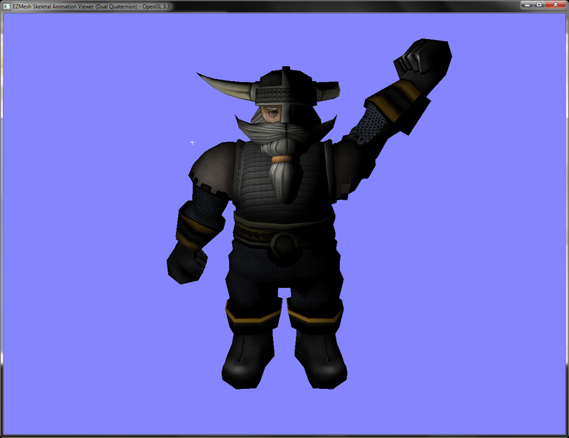
dwarf_anim.ezm skeletal model. Even with extreme rotation at the shoulder joint, the output does not suffer from candy wrapper artefacts as shown in the following figure:
hand, if we use the matrix palette skinning, we get the following output, which clearly shows the candy wrapper artefacts:
- Skinning with Dual Quaternions at http://isg.cs.tcd.ie/projects/DualQuaternions/
- Skinning with Dual Quaternions demo in NVIDIA DirectX sdk 10.5 at http://developer.download.nvidia.com/SDK/10.5/direct3d/samples.html
- Dual Quaternion Google Summer of Code 2011 implementation in OGRE at http://www.ogre3d.org/tikiwiki/tiki-index.php?page=SoC2011%20Dual%20Quaternion%20Skinning
- http://isg.cs.tcd.ie/projects/DualQuaternions/
- Skinning with Dual Quaternions demo in NVIDIA DirectX sdk 10.5 at http://developer.download.nvidia.com/SDK/10.5/direct3d/samples.html
- Dual Quaternion Google Summer of Code 2011 implementation in OGRE at http://www.ogre3d.org/tikiwiki/tiki-index.php?page=SoC2011%20Dual%20Quaternion%20Skinning
In this recipe we will use the transform feedback mechanism of the modern GPU to model cloth. Transform feedback is a special mode of modern GPU in which the vertex shader can directly output to a buffer object. This allows developers to do complex computations without affecting the rest of the rendering pipeline. We will elaborate how to use this mechanism to simulate cloth entirely on the GPU.
From the implementation point of view in modern OpenGL, transform feedback exists as an OpenGL object similar to textures. Working with transform feedback object requires two steps: first, generation of transform feedback with specification of shader outputs, and second, usage of the transform feedback for simulation and rendering. We generate it by calling the glGetTransformFeedbacks function and passing it the number of objects and the variable to store the returned IDs. After the object is created, it is bound to the current OpenGL context by calling glBindTransformFeedback, and its only parameter is the ID of the transform feedback object we are interested to bind.
Next, we need to register the vertex attributes that we want to record in a transform feedback buffer. This is done through the glTransformFeedbackVaryings function. The parameters this function requires are in the following order: the shader program object, the number of outputs from the shader, the names of the attributes, and the recording mode. Recording mode can be either GL_INTERLEAVED_ATTRIBS (which means that the attributes will all be stored in a single interleaved buffer object) or GL_SEPARATE_ATTRIBS (which means each attribute will be stored in its own buffer object). Note that the shader program has to be relinked after the shader output varyings are specified.
We also have to set up our buffer objects that are going to store the attributes' output through transform feedback. At the rendering stage, we first set up our shader and the required uniforms. Then, we bind out vertex array objects storing out buffer object binding. Next, we bind the buffer object for transform feedback by calling the glBindBufferBase function. The first parameter is the index and the second parameter is the buffer object ID, which will store the shader output attribute. We can bind as many objects as we need, but the total calls to this function must be at least equal to the total output attributes from the vertex shader. Once the buffers are bound, we can initiate transform feedback by issuing a call to glBeginTransformFeedback and the parameter to this function is the output primitive type. We then issue our glDraw* call and then call glEndTransformFeedback.
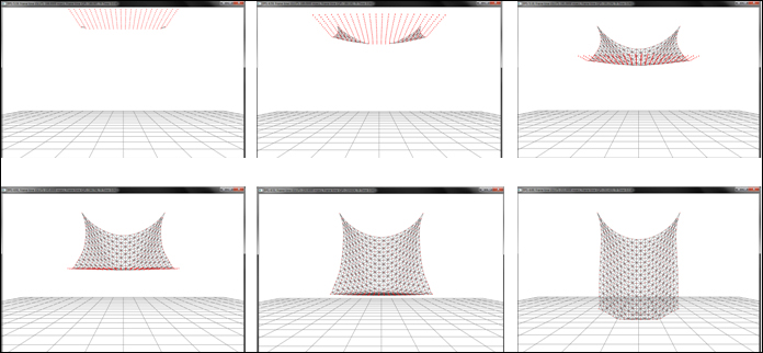
For the cloth simulation implementation using transform feedback, this is how we proceed. We store the current and previous position of the cloth vertices into a pair of buffer objects. To have convenient access to the buffer objects, we store these into a pair of vertex array objects. Then in order to deform the cloth, we run a vertex shader that inputs the current and previous positions from the buffer objects. In the vertex shader, the internal and external forces are calculated for each pair of cloth vertices and then acceleration is calculated. Using Verlet integration, the new vertex position is obtained. The new and previous positions are output from the vertex shader, so they are written out to the attached transform feedback buffers. Since we have a pair of vertex array objects, we ping pong between the two. This process is continued and the simulation proceeds forward.
The whole process is well summarized by the following figure:

Let us start the recipe by following these simple steps:
- Generate the geometry and topology for a piece of cloth by creating a set of points and their connectivity. Bind this data to a buffer object. The vectors
XandX_laststore the current and last position respectively, and the vectorFstores the force for each vertex:vector<GLushort> indices; vector<glm::vec4> X; vector<glm::vec4> X_last; vector<glm::vec3> F; indices.resize( numX*numY*2*3); X.resize(total_points); X_last.resize(total_points); F.resize(total_points); for(int j=0;j<=numY;j++) { for(int i=0;i<=numX;i++) { X[count] = glm::vec4( ((float(i)/(u-1)) *2-1)* hsize, sizeX+1, ((float(j)/(v-1) )* sizeY),1); X_last[count] = X[count]; count++; } } GLushort* id=&indices[0]; for (int i = 0; i < numY; i++) { for (int j = 0; j < numX; j++) { int i0 = i * (numX+1) + j; int i1 = i0 + 1; int i2 = i0 + (numX+1); int i3 = i2 + 1; if ((j+i)%2) { *id++ = i0; *id++ = i2; *id++ = i1; *id++ = i1; *id++ = i2; *id++ = i3; } else { *id++ = i0; *id++ = i2; *id++ = i3; *id++ = i0; *id++ = i3; *id++ = i1; } } } glGenVertexArrays(1, &clothVAOID); glGenBuffers (1, &clothVBOVerticesID); glGenBuffers (1, &clothVBOIndicesID); glBindVertexArray(clothVAOID); glBindBuffer (GL_ARRAY_BUFFER, clothVBOVerticesID); glBufferData (GL_ARRAY_BUFFER, sizeof(float)*4*X.size(), &X[0].x, GL_STATIC_DRAW); glEnableVertexAttribArray(0); glVertexAttribPointer (0, 4, GL_FLOAT, GL_FALSE,0,0); glBindBuffer(GL_ELEMENT_ARRAY_BUFFER, clothVBOIndicesID); glBufferData(GL_ELEMENT_ARRAY_BUFFER, sizeof(GLushort)*indices.size(), &indices[0], GL_STATIC_DRAW); glBindVertexArray(0); - Create two pairs of vertex array objects (VAO), one pair for rendering and another pair for update of points. Bind two buffer objects (containing current positions and previous positions) to the update VAO, and one buffer object (containing current positions) to the render VAO. Also attach an element array buffer for geometry indices. Set the buffer object usage parameter as
GL_DYNAMIC_COPY). This usage parameter hints to the GPU that the contents of the buffer object will be frequently changed, and it will be read in OpenGL or used as a source for GL commands:glGenVertexArrays(2, vaoUpdateID); glGenVertexArrays(2, vaoRenderID); glGenBuffers( 2, vboID_Pos); glGenBuffers( 2, vboID_PrePos); for(int i=0;i<2;i++) { glBindVertexArray(vaoUpdateID[i]); glBindBuffer( GL_ARRAY_BUFFER, vboID_Pos[i]); glBufferData( GL_ARRAY_BUFFER, X.size()* sizeof(glm::vec4), &(X[0].x), GL_DYNAMIC_COPY); glEnableVertexAttribArray(0); glVertexAttribPointer(0, 4, GL_FLOAT, GL_FALSE, 0, 0); glBindBuffer( GL_ARRAY_BUFFER, vboID_PrePos[i]); glBufferData( GL_ARRAY_BUFFER, X_last.size()*sizeof(glm::vec4), &(X_last[0].x), GL_DYNAMIC_COPY); glEnableVertexAttribArray(1); glVertexAttribPointer(1, 4, GL_FLOAT, GL_FALSE, 0,0); } //set render vao for(int i=0;i<2;i++) { glBindVertexArray(vaoRenderID[i]); glBindBuffer( GL_ARRAY_BUFFER, vboID_Pos[i]); glEnableVertexAttribArray(0); glVertexAttribPointer(0, 4, GL_FLOAT, GL_FALSE, 0, 0); glBindBuffer(GL_ELEMENT_ARRAY_BUFFER, vboIndices); if(i==0) glBufferData(GL_ELEMENT_ARRAY_BUFFER, indices.size()*sizeof(GLushort), &indices[0], GL_STATIC_DRAW); } - For ease of access in the vertex shader, bind the current and previous position buffer objects to a set of buffer textures. The buffer textures are one dimensional textures that are created like normal OpenGL textures using the
glGenTexturescall, but they are bound to theGL_TEXTURE_BUFFERtarget. They provide read access to the entire buffer object memory in the vertex shader. The data is accessed in the vertex shader using thetexelFetchBufferfunction:for(int i=0;i<2;i++) { glBindTexture( GL_TEXTURE_BUFFER, texPosID[i]); glTexBuffer( GL_TEXTURE_BUFFER, GL_RGBA32F, vboID_Pos[i]); glBindTexture( GL_TEXTURE_BUFFER, texPrePosID[i]); glTexBuffer(GL_TEXTURE_BUFFER, GL_RGBA32F, vboID_PrePos[i]); } - Generate a transform feedback object and pass the attribute names that will be output from our deformation vertex shader. Make sure to relink the program.
glGenTransformFeedbacks(1, &tfID); glBindTransformFeedback(GL_TRANSFORM_FEEDBACK, tfID); const char* varying_names[]={"out_position_mass", "out_prev_position"}; glTransformFeedbackVaryings(massSpringShader.GetProgram(), 2, varying_names, GL_SEPARATE_ATTRIBS); glLinkProgram(massSpringShader.GetProgram()); - In the rendering function, bind the cloth deformation shader (
Chapter8/TransformFeedbackCloth/shaders/Spring.vert) and then run a loop. In each loop iteration, bind the texture buffers, and then bind the update vertex array object. At the same time, bind the previous buffer objects as the transform feedback buffers. These will store the output from the vertex shader. Disable the rasterizer, begin the transform feedback mode, and then draw the entire set of cloth vertices. Use the ping pong approach to swap the read/write pathways:massSpringShader.Use(); glUniformMatrix4fv(massSpringShader("MVP"), 1, GL_FALSE, glm::value_ptr(mMVP)); for(int i=0;i<NUM_ITER;i++) { glActiveTexture( GL_TEXTURE0); glBindTexture( GL_TEXTURE_BUFFER, texPosID[writeID]); glActiveTexture( GL_TEXTURE1); glBindTexture( GL_TEXTURE_BUFFER, texPrePosID[writeID]); glBindVertexArray( vaoUpdateID[writeID]); glBindBufferBase(GL_TRANSFORM_FEEDBACK_BUFFER, 0, vboID_Pos[readID]); glBindBufferBase(GL_TRANSFORM_FEEDBACK_BUFFER, 1, vboID_PrePos[readID]); glEnable(GL_RASTERIZER_DISCARD); // disable rasrization glBeginQuery(GL_TIME_ELAPSED,t_query); glBeginTransformFeedback(GL_POINTS); glDrawArrays(GL_POINTS, 0, total_points); glEndTransformFeedback(); glEndQuery(GL_TIME_ELAPSED); glFlush(); glDisable(GL_RASTERIZER_DISCARD); int tmp = readID; readID=writeID; writeID = tmp; } glGetQueryObjectui64v(t_query, GL_QUERY_RESULT, &elapsed_time); delta_time = elapsed_time / 1000000.0f; massSpringShader.UnUse(); - After the loop is terminated, bind the render VAO that renders the cloth geometry and vertices:
glBindVertexArray(vaoRenderID[writeID]); glDisable(GL_DEPTH_TEST); renderShader.Use(); glUniformMatrix4fv(renderShader("MVP"), 1, GL_FALSE, glm::value_ptr(mMVP)); glDrawElements(GL_TRIANGLES, indices.size(), GL_UNSIGNED_SHORT,0); renderShader.UnUse(); glEnable(GL_DEPTH_TEST); if(bDisplayMasses) { particleShader.Use(); glUniform1i(particleShader("selected_index"), selected_index); glUniformMatrix4fv(particleShader("MV"), 1, GL_FALSE, glm::value_ptr(mMV)); glUniformMatrix4fv(particleShader("MVP"), 1, GL_FALSE, glm::value_ptr(mMVP)); glDrawArrays(GL_POINTS, 0, total_points); particleShader.UnUse(); } glBindVertexArray( 0); - In the vertex shader, obtain the current and previous position of the cloth vertex. If the vertex is a pinned vertex, set its mass to
0so it would not be simulated; otherwise, add an external force based on gravity. Next loop through all neighbors of the current vertex by looking up the texture buffer and estimate the internal force:float m = position_mass.w; vec3 pos = position_mass.xyz; vec3 pos_old = prev_position.xyz; vec3 vel = (pos - pos_old) / dt; float ks=0, kd=0; int index = gl_VertexID; int ix = index % texsize_x; int iy = index / texsize_x; if(index ==0 || index == (texsize_x-1)) m = 0; vec3 F = gravity*m + (DEFAULT_DAMPING*vel); for(int k=0;k<12;k++) { ivec2 coord = getNextNeighbor(k, ks, kd); int j = coord.x; int i = coord.y; if (((iy + i) < 0) || ((iy + i) > (texsize_y-1))) continue; if (((ix + j) < 0) || ((ix + j) > (texsize_x-1))) continue; int index_neigh = (iy + i) * texsize_x + ix + j; vec3 p2 = texelFetchBuffer(tex_position_mass, index_neigh).xyz; vec3 p2_last = texelFetchBuffer(tex_prev_position_mass, index_neigh).xyz; vec2 coord_neigh = vec2(ix + j, iy + i)*step; float rest_length = length(coord*inv_cloth_size); vec3 v2 = (p2- p2_last)/dt; vec3 deltaP = pos - p2; vec3 deltaV = vel - v2; float dist = length(deltaP); float leftTerm = -ks * (dist-rest_length); float rightTerm = kd * (dot(deltaV, deltaP)/dist); vec3 springForce = (leftTerm + rightTerm)* normalize(deltaP); F += springForce; } - Using the combined force, calculate the acceleration and then estimate the new position using Verlet integration. Output the appropriate attribute from the shader:
vec3 acc = vec3(0); if(m!=0) acc = F/m; vec3 tmp = pos; pos = pos * 2.0 - pos_old + acc* dt * dt; pos_old = tmp; pos.y=max(0, pos.y); out_position_mass = vec4(pos, m); out_prev_position = vec4(pos_old,m); gl_Position = MVP*vec4(pos, 1);
There are two parts of this recipe, the generation of geometry and identifying output attributes for transform feedback buffers. We first generate the cloth geometry and then associate our buffer objects. To enable easier access of current and previous positions, we bind the position buffer objects as texture buffers.
Next, the acceleration due to gravity and velocity damping force is applied. After this, a loop is run which basically loops through all of the neighbors of the current vertex and estimates the net internal (spring) force. This force is then added to the combined force for the current vertex:
The shader, along with the transform feedback mechanism, proceeds to deform all of the cloth vertices and in the end, we get the cloth vertices deformed.
X and X_last store the current and last position respectively, and the vector F stores the force for each vertex:
vector<GLushort> indices;
vector<glm::vec4> X;
vector<glm::vec4> X_last;
vector<glm::vec3> F;
indices.resize( numX*numY*2*3);
X.resize(total_points);
X_last.resize(total_points);
F.resize(total_points);
for(int j=0;j<=numY;j++) {
for(int i=0;i<=numX;i++) {
X[count] = glm::vec4( ((float(i)/(u-1)) *2-1)* hsize,
sizeX+1, ((float(j)/(v-1) )* sizeY),1);
X_last[count] = X[count];
count++;
}
}
GLushort* id=&indices[0];
for (int i = 0; i < numY; i++) {
for (int j = 0; j < numX; j++) {
int i0 = i * (numX+1) + j;
int i1 = i0 + 1;
int i2 = i0 + (numX+1);
int i3 = i2 + 1;
if ((j+i)%2) {
*id++ = i0; *id++ = i2; *id++ = i1;
*id++ = i1; *id++ = i2; *id++ = i3;
} else {
*id++ = i0; *id++ = i2; *id++ = i3;
*id++ = i0; *id++ = i3; *id++ = i1;
}
}
}
glGenVertexArrays(1, &clothVAOID);
glGenBuffers (1, &clothVBOVerticesID);
glGenBuffers (1, &clothVBOIndicesID);
glBindVertexArray(clothVAOID);
glBindBuffer (GL_ARRAY_BUFFER, clothVBOVerticesID);
glBufferData (GL_ARRAY_BUFFER, sizeof(float)*4*X.size(),
&X[0].x, GL_STATIC_DRAW);
glEnableVertexAttribArray(0);
glVertexAttribPointer (0, 4, GL_FLOAT, GL_FALSE,0,0);
glBindBuffer(GL_ELEMENT_ARRAY_BUFFER, clothVBOIndicesID);
glBufferData(GL_ELEMENT_ARRAY_BUFFER,
sizeof(GLushort)*indices.size(), &indices[0], GL_STATIC_DRAW);
glBindVertexArray(0);- vertex array objects (VAO), one pair for rendering and another pair for update of points. Bind two buffer objects (containing current positions and previous positions) to the update VAO, and one buffer object (containing current positions) to the render VAO. Also attach an element array buffer for geometry indices. Set the buffer object usage parameter as
GL_DYNAMIC_COPY). This usage parameter hints to the GPU that the contents of the buffer object will be frequently changed, and it will be read in OpenGL or used as a source for GL commands:glGenVertexArrays(2, vaoUpdateID); glGenVertexArrays(2, vaoRenderID); glGenBuffers( 2, vboID_Pos); glGenBuffers( 2, vboID_PrePos); for(int i=0;i<2;i++) { glBindVertexArray(vaoUpdateID[i]); glBindBuffer( GL_ARRAY_BUFFER, vboID_Pos[i]); glBufferData( GL_ARRAY_BUFFER, X.size()* sizeof(glm::vec4), &(X[0].x), GL_DYNAMIC_COPY); glEnableVertexAttribArray(0); glVertexAttribPointer(0, 4, GL_FLOAT, GL_FALSE, 0, 0); glBindBuffer( GL_ARRAY_BUFFER, vboID_PrePos[i]); glBufferData( GL_ARRAY_BUFFER, X_last.size()*sizeof(glm::vec4), &(X_last[0].x), GL_DYNAMIC_COPY); glEnableVertexAttribArray(1); glVertexAttribPointer(1, 4, GL_FLOAT, GL_FALSE, 0,0); } //set render vao for(int i=0;i<2;i++) { glBindVertexArray(vaoRenderID[i]); glBindBuffer( GL_ARRAY_BUFFER, vboID_Pos[i]); glEnableVertexAttribArray(0); glVertexAttribPointer(0, 4, GL_FLOAT, GL_FALSE, 0, 0); glBindBuffer(GL_ELEMENT_ARRAY_BUFFER, vboIndices); if(i==0) glBufferData(GL_ELEMENT_ARRAY_BUFFER, indices.size()*sizeof(GLushort), &indices[0], GL_STATIC_DRAW); } - For ease of access in the vertex shader, bind the current and previous position buffer objects to a set of buffer textures. The buffer textures are one dimensional textures that are created like normal OpenGL textures using the
glGenTexturescall, but they are bound to theGL_TEXTURE_BUFFERtarget. They provide read access to the entire buffer object memory in the vertex shader. The data is accessed in the vertex shader using thetexelFetchBufferfunction:for(int i=0;i<2;i++) { glBindTexture( GL_TEXTURE_BUFFER, texPosID[i]); glTexBuffer( GL_TEXTURE_BUFFER, GL_RGBA32F, vboID_Pos[i]); glBindTexture( GL_TEXTURE_BUFFER, texPrePosID[i]); glTexBuffer(GL_TEXTURE_BUFFER, GL_RGBA32F, vboID_PrePos[i]); } - Generate a transform feedback object and pass the attribute names that will be output from our deformation vertex shader. Make sure to relink the program.
glGenTransformFeedbacks(1, &tfID); glBindTransformFeedback(GL_TRANSFORM_FEEDBACK, tfID); const char* varying_names[]={"out_position_mass", "out_prev_position"}; glTransformFeedbackVaryings(massSpringShader.GetProgram(), 2, varying_names, GL_SEPARATE_ATTRIBS); glLinkProgram(massSpringShader.GetProgram()); - In the rendering function, bind the cloth deformation shader (
Chapter8/TransformFeedbackCloth/shaders/Spring.vert) and then run a loop. In each loop iteration, bind the texture buffers, and then bind the update vertex array object. At the same time, bind the previous buffer objects as the transform feedback buffers. These will store the output from the vertex shader. Disable the rasterizer, begin the transform feedback mode, and then draw the entire set of cloth vertices. Use the ping pong approach to swap the read/write pathways:massSpringShader.Use(); glUniformMatrix4fv(massSpringShader("MVP"), 1, GL_FALSE, glm::value_ptr(mMVP)); for(int i=0;i<NUM_ITER;i++) { glActiveTexture( GL_TEXTURE0); glBindTexture( GL_TEXTURE_BUFFER, texPosID[writeID]); glActiveTexture( GL_TEXTURE1); glBindTexture( GL_TEXTURE_BUFFER, texPrePosID[writeID]); glBindVertexArray( vaoUpdateID[writeID]); glBindBufferBase(GL_TRANSFORM_FEEDBACK_BUFFER, 0, vboID_Pos[readID]); glBindBufferBase(GL_TRANSFORM_FEEDBACK_BUFFER, 1, vboID_PrePos[readID]); glEnable(GL_RASTERIZER_DISCARD); // disable rasrization glBeginQuery(GL_TIME_ELAPSED,t_query); glBeginTransformFeedback(GL_POINTS); glDrawArrays(GL_POINTS, 0, total_points); glEndTransformFeedback(); glEndQuery(GL_TIME_ELAPSED); glFlush(); glDisable(GL_RASTERIZER_DISCARD); int tmp = readID; readID=writeID; writeID = tmp; } glGetQueryObjectui64v(t_query, GL_QUERY_RESULT, &elapsed_time); delta_time = elapsed_time / 1000000.0f; massSpringShader.UnUse(); - After the loop is terminated, bind the render VAO that renders the cloth geometry and vertices:
glBindVertexArray(vaoRenderID[writeID]); glDisable(GL_DEPTH_TEST); renderShader.Use(); glUniformMatrix4fv(renderShader("MVP"), 1, GL_FALSE, glm::value_ptr(mMVP)); glDrawElements(GL_TRIANGLES, indices.size(), GL_UNSIGNED_SHORT,0); renderShader.UnUse(); glEnable(GL_DEPTH_TEST); if(bDisplayMasses) { particleShader.Use(); glUniform1i(particleShader("selected_index"), selected_index); glUniformMatrix4fv(particleShader("MV"), 1, GL_FALSE, glm::value_ptr(mMV)); glUniformMatrix4fv(particleShader("MVP"), 1, GL_FALSE, glm::value_ptr(mMVP)); glDrawArrays(GL_POINTS, 0, total_points); particleShader.UnUse(); } glBindVertexArray( 0); - In the vertex shader, obtain the current and previous position of the cloth vertex. If the vertex is a pinned vertex, set its mass to
0so it would not be simulated; otherwise, add an external force based on gravity. Next loop through all neighbors of the current vertex by looking up the texture buffer and estimate the internal force:float m = position_mass.w; vec3 pos = position_mass.xyz; vec3 pos_old = prev_position.xyz; vec3 vel = (pos - pos_old) / dt; float ks=0, kd=0; int index = gl_VertexID; int ix = index % texsize_x; int iy = index / texsize_x; if(index ==0 || index == (texsize_x-1)) m = 0; vec3 F = gravity*m + (DEFAULT_DAMPING*vel); for(int k=0;k<12;k++) { ivec2 coord = getNextNeighbor(k, ks, kd); int j = coord.x; int i = coord.y; if (((iy + i) < 0) || ((iy + i) > (texsize_y-1))) continue; if (((ix + j) < 0) || ((ix + j) > (texsize_x-1))) continue; int index_neigh = (iy + i) * texsize_x + ix + j; vec3 p2 = texelFetchBuffer(tex_position_mass, index_neigh).xyz; vec3 p2_last = texelFetchBuffer(tex_prev_position_mass, index_neigh).xyz; vec2 coord_neigh = vec2(ix + j, iy + i)*step; float rest_length = length(coord*inv_cloth_size); vec3 v2 = (p2- p2_last)/dt; vec3 deltaP = pos - p2; vec3 deltaV = vel - v2; float dist = length(deltaP); float leftTerm = -ks * (dist-rest_length); float rightTerm = kd * (dot(deltaV, deltaP)/dist); vec3 springForce = (leftTerm + rightTerm)* normalize(deltaP); F += springForce; } - Using the combined force, calculate the acceleration and then estimate the new position using Verlet integration. Output the appropriate attribute from the shader:
vec3 acc = vec3(0); if(m!=0) acc = F/m; vec3 tmp = pos; pos = pos * 2.0 - pos_old + acc* dt * dt; pos_old = tmp; pos.y=max(0, pos.y); out_position_mass = vec4(pos, m); out_prev_position = vec4(pos_old,m); gl_Position = MVP*vec4(pos, 1);
There are two parts of this recipe, the generation of geometry and identifying output attributes for transform feedback buffers. We first generate the cloth geometry and then associate our buffer objects. To enable easier access of current and previous positions, we bind the position buffer objects as texture buffers.
Next, the acceleration due to gravity and velocity damping force is applied. After this, a loop is run which basically loops through all of the neighbors of the current vertex and estimates the net internal (spring) force. This force is then added to the combined force for the current vertex:
The shader, along with the transform feedback mechanism, proceeds to deform all of the cloth vertices and in the end, we get the cloth vertices deformed.
parts of this recipe, the generation of geometry and identifying output attributes for transform feedback buffers. We first generate the cloth geometry and then associate our buffer objects. To enable easier access of current and previous positions, we bind the position buffer objects as texture buffers.
Next, the acceleration due to gravity and velocity damping force is applied. After this, a loop is run which basically loops through all of the neighbors of the current vertex and estimates the net internal (spring) force. This force is then added to the combined force for the current vertex:
The shader, along with the transform feedback mechanism, proceeds to deform all of the cloth vertices and in the end, we get the cloth vertices deformed.
In this recipe, we will build on top of the previous recipe and add collision detection and response to the cloth model.
Let us start this recipe by following these simple steps:
- Generate the geometry and topology for a piece of cloth by creating a set of points and their connectivity. Bind this data to a buffer object as in the previous recipe.
- Set up a pair of vertex array objects and buffer objects as in the previous recipe. Also attach buffer textures for easier access to the buffer object memory in the vertex shader.
- Generate a transform feedback object and pass the attribute names that will be output from our deformation vertex shader. Make sure to relink the program again:
glGenTransformFeedbacks(1, &tfID); glBindTransformFeedback(GL_TRANSFORM_FEEDBACK, tfID); const char* varying_names[]={"out_position_mass", "out_prev_position"}; glTransformFeedbackVaryings(massSpringShader.GetProgram(), 2, varying_names, GL_SEPARATE_ATTRIBS); glLinkProgram(massSpringShader.GetProgram()); - Generate an ellipsoid object by using a simple 4×4 matrix. Also store the inverse of the ellipsoid's transform. The location of the ellipsoid is stored by the translate matrix, the orientation by the rotate matrix, and the non-uniform scaling by the scale matrix as follows. When applied, the matrices work in the opposite order. The non-uniform scaling causes the sphere to compress in the Z direction first. Then, the rotation orients the ellipsoid such that it is rotated by 45 degrees on the X axis. Finally, the ellipsoid is shifted by 2 units on the Y axis:
ellipsoid = glm::translate(glm::mat4(1),glm::vec3(0,2,0)); ellipsoid = glm::rotate(ellipsoid, 45.0f ,glm::vec3(1,0,0)); ellipsoid = glm::scale(ellipsoid, glm::vec3(fRadius,fRadius,fRadius/2)); inverse_ellipsoid = glm::inverse(ellipsoid);
- In the rendering function, bind the cloth deformation shader (
Chapter8/ TransformFeedbackClothCollision/shaders/Spring.vert) and then run a loop. In each iteration, bind the texture buffers, and then bind the update vertex array object. At the same time, bind the previous buffer objects as the transform feedback buffers. Do the ping pong strategy as in the previous recipe. - After the loop is terminated, bind the render VAO and render the cloth:
glBindVertexArray(vaoRenderID[writeID]); glDisable(GL_DEPTH_TEST); renderShader.Use(); glUniformMatrix4fv(renderShader("MVP"), 1, GL_FALSE, glm::value_ptr(mMVP)); glDrawElements(GL_TRIANGLES, indices.size(), GL_UNSIGNED_SHORT,0); renderShader.UnUse(); glEnable(GL_DEPTH_TEST); if(bDisplayMasses) { particleShader.Use(); glUniform1i(particleShader("selected_index"), selected_index); glUniformMatrix4fv(particleShader("MV"), 1, GL_FALSE, glm::value_ptr(mMV)); glUniformMatrix4fv(particleShader("MVP"), 1, GL_FALSE, glm::value_ptr(mMVP)); glDrawArrays(GL_POINTS, 0, total_points); particleShader.UnUse(); } glBindVertexArray( 0); - In the vertex shader, obtain the current and previous position of the cloth vertex. If the vertex is a pinned vertex, set its mass to
0so it would not be simulated, otherwise, add an external force based on gravity. Next, loop through all neighbors of the current vertex by looking up the texture buffer and estimate the internal force:float m = position_mass.w; vec3 pos = position_mass.xyz; vec3 pos_old = prev_position.xyz; vec3 vel = (pos - pos_old) / dt; float ks=0, kd=0; int index = gl_VertexID; int ix = index % texsize_x; int iy = index / texsize_x; if(index ==0 || index == (texsize_x-1)) m = 0; vec3 F = gravity*m + (DEFAULT_DAMPING*vel); for(int k=0;k<12;k++) { ivec2 coord = getNextNeighbor(k, ks, kd); int j = coord.x; int i = coord.y; if (((iy + i) < 0) || ((iy + i) > (texsize_y-1))) continue; if (((ix + j) < 0) || ((ix + j) > (texsize_x-1))) continue; int index_neigh = (iy + i) * texsize_x + ix + j; vec3 p2 = texelFetchBuffer(tex_position_mass, index_neigh).xyz; vec3 p2_last = texelFetchBuffer(tex_prev_position_mass, index_neigh).xyz; vec2 coord_neigh = vec2(ix + j, iy + i)*step; float rest_length = length(coord*inv_cloth_size); vec3 v2 = (p2- p2_last)/dt; vec3 deltaP = pos - p2; vec3 deltaV = vel - v2; float dist = length(deltaP); float leftTerm = -ks * (dist-rest_length); float rightTerm = kd * (dot(deltaV, deltaP)/dist); vec3 springForce = (leftTerm + rightTerm)* normalize(deltaP); F += springForce; } - Using the combined force, calculate the acceleration and then estimate the new position using Verlet integration. Output the appropriate attribute from the shader:
vec3 acc = vec3(0); if(m!=0) acc = F/m; vec3 tmp = pos; pos = pos * 2.0 - pos_old + acc* dt * dt; pos_old = tmp; pos.y=max(0, pos.y); - After applying the floor collision, check for collision with an ellipsoid. If there is a collision, modify the position such that the collision is resolved. Finally, output the appropriate attributes from the vertex shader.
vec4 x0 = inv_ellipsoid*vec4(pos,1); vec3 delta0 = x0.xyz-ellipsoid.xyz; float dist2 = dot(delta0, delta0); if(dist2<1) { delta0 = (ellipsoid.w - dist2) * delta0 / dist2; vec3 delta; vec3 transformInv = vec3(ellipsoid_xform[0].x, ellipsoid_xform[1].x, ellipsoid_xform[2].x); transformInv /= dot(transformInv, transformInv); delta.x = dot(delta0, transformInv); transformInv = vec3(ellipsoid_xform[0].y, ellipsoid_xform[1].y, ellipsoid_xform[2].y); transformInv /= dot(transformInv, transformInv); delta.y = dot(delta0, transformInv); transformInv = vec3(ellipsoid_xform[0].z, ellipsoid_xform[1].z, ellipsoid_xform[2].z); transformInv /= dot(transformInv, transformInv); delta.z = dot(delta0, transformInv); pos += delta ; pos_old = pos; } out_position_mass = vec4(pos, m); out_prev_position = vec4(pos_old,m); gl_Position = MVP*vec4(pos, 1);
The cloth deformation vertex shader has some additional lines of code to enable collision detection and response. For detection of collision with a plane, we can simply put the current position in the plane equation to find the distance of the current vertex from the plane. If it is less than 0, we have passed through the plane, in which case, we can move the vertex back in the plane's normal direction.
The demo application implementing this recipe renders a piece of cloth fixed at two points and is allowed to fall under gravity. In addition, there is an oriented ellipsoid with which the cloth collides as shown in the following figure:
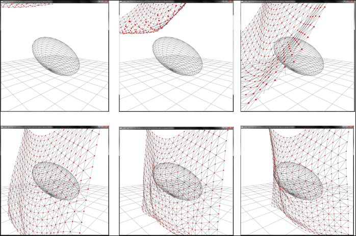
Although we have touched upon basic collision primitives, like spheres, oriented ellipsoids, and plane, more complex primitives can be implemented with the combination of these basic primitives. In addition, polygonal primitives can also be implemented. We leave that as an exercise for the reader.
Chapter8/TransformFeedbackClothCollision directory. For this recipe, the setup code and rendering code remains the same as in the previous recipe. The only change is the addition of the ellipsoid/sphere collision code.
Let us start this recipe by following these simple steps:
- Generate the geometry and topology for a piece of cloth by creating a set of points and their connectivity. Bind this data to a buffer object as in the previous recipe.
- Set up a pair of vertex array objects and buffer objects as in the previous recipe. Also attach buffer textures for easier access to the buffer object memory in the vertex shader.
- Generate a transform feedback object and pass the attribute names that will be output from our deformation vertex shader. Make sure to relink the program again:
glGenTransformFeedbacks(1, &tfID); glBindTransformFeedback(GL_TRANSFORM_FEEDBACK, tfID); const char* varying_names[]={"out_position_mass", "out_prev_position"}; glTransformFeedbackVaryings(massSpringShader.GetProgram(), 2, varying_names, GL_SEPARATE_ATTRIBS); glLinkProgram(massSpringShader.GetProgram()); - Generate an ellipsoid object by using a simple 4×4 matrix. Also store the inverse of the ellipsoid's transform. The location of the ellipsoid is stored by the translate matrix, the orientation by the rotate matrix, and the non-uniform scaling by the scale matrix as follows. When applied, the matrices work in the opposite order. The non-uniform scaling causes the sphere to compress in the Z direction first. Then, the rotation orients the ellipsoid such that it is rotated by 45 degrees on the X axis. Finally, the ellipsoid is shifted by 2 units on the Y axis:
ellipsoid = glm::translate(glm::mat4(1),glm::vec3(0,2,0)); ellipsoid = glm::rotate(ellipsoid, 45.0f ,glm::vec3(1,0,0)); ellipsoid = glm::scale(ellipsoid, glm::vec3(fRadius,fRadius,fRadius/2)); inverse_ellipsoid = glm::inverse(ellipsoid);
- In the rendering function, bind the cloth deformation shader (
Chapter8/ TransformFeedbackClothCollision/shaders/Spring.vert) and then run a loop. In each iteration, bind the texture buffers, and then bind the update vertex array object. At the same time, bind the previous buffer objects as the transform feedback buffers. Do the ping pong strategy as in the previous recipe. - After the loop is terminated, bind the render VAO and render the cloth:
glBindVertexArray(vaoRenderID[writeID]); glDisable(GL_DEPTH_TEST); renderShader.Use(); glUniformMatrix4fv(renderShader("MVP"), 1, GL_FALSE, glm::value_ptr(mMVP)); glDrawElements(GL_TRIANGLES, indices.size(), GL_UNSIGNED_SHORT,0); renderShader.UnUse(); glEnable(GL_DEPTH_TEST); if(bDisplayMasses) { particleShader.Use(); glUniform1i(particleShader("selected_index"), selected_index); glUniformMatrix4fv(particleShader("MV"), 1, GL_FALSE, glm::value_ptr(mMV)); glUniformMatrix4fv(particleShader("MVP"), 1, GL_FALSE, glm::value_ptr(mMVP)); glDrawArrays(GL_POINTS, 0, total_points); particleShader.UnUse(); } glBindVertexArray( 0); - In the vertex shader, obtain the current and previous position of the cloth vertex. If the vertex is a pinned vertex, set its mass to
0so it would not be simulated, otherwise, add an external force based on gravity. Next, loop through all neighbors of the current vertex by looking up the texture buffer and estimate the internal force:float m = position_mass.w; vec3 pos = position_mass.xyz; vec3 pos_old = prev_position.xyz; vec3 vel = (pos - pos_old) / dt; float ks=0, kd=0; int index = gl_VertexID; int ix = index % texsize_x; int iy = index / texsize_x; if(index ==0 || index == (texsize_x-1)) m = 0; vec3 F = gravity*m + (DEFAULT_DAMPING*vel); for(int k=0;k<12;k++) { ivec2 coord = getNextNeighbor(k, ks, kd); int j = coord.x; int i = coord.y; if (((iy + i) < 0) || ((iy + i) > (texsize_y-1))) continue; if (((ix + j) < 0) || ((ix + j) > (texsize_x-1))) continue; int index_neigh = (iy + i) * texsize_x + ix + j; vec3 p2 = texelFetchBuffer(tex_position_mass, index_neigh).xyz; vec3 p2_last = texelFetchBuffer(tex_prev_position_mass, index_neigh).xyz; vec2 coord_neigh = vec2(ix + j, iy + i)*step; float rest_length = length(coord*inv_cloth_size); vec3 v2 = (p2- p2_last)/dt; vec3 deltaP = pos - p2; vec3 deltaV = vel - v2; float dist = length(deltaP); float leftTerm = -ks * (dist-rest_length); float rightTerm = kd * (dot(deltaV, deltaP)/dist); vec3 springForce = (leftTerm + rightTerm)* normalize(deltaP); F += springForce; } - Using the combined force, calculate the acceleration and then estimate the new position using Verlet integration. Output the appropriate attribute from the shader:
vec3 acc = vec3(0); if(m!=0) acc = F/m; vec3 tmp = pos; pos = pos * 2.0 - pos_old + acc* dt * dt; pos_old = tmp; pos.y=max(0, pos.y); - After applying the floor collision, check for collision with an ellipsoid. If there is a collision, modify the position such that the collision is resolved. Finally, output the appropriate attributes from the vertex shader.
vec4 x0 = inv_ellipsoid*vec4(pos,1); vec3 delta0 = x0.xyz-ellipsoid.xyz; float dist2 = dot(delta0, delta0); if(dist2<1) { delta0 = (ellipsoid.w - dist2) * delta0 / dist2; vec3 delta; vec3 transformInv = vec3(ellipsoid_xform[0].x, ellipsoid_xform[1].x, ellipsoid_xform[2].x); transformInv /= dot(transformInv, transformInv); delta.x = dot(delta0, transformInv); transformInv = vec3(ellipsoid_xform[0].y, ellipsoid_xform[1].y, ellipsoid_xform[2].y); transformInv /= dot(transformInv, transformInv); delta.y = dot(delta0, transformInv); transformInv = vec3(ellipsoid_xform[0].z, ellipsoid_xform[1].z, ellipsoid_xform[2].z); transformInv /= dot(transformInv, transformInv); delta.z = dot(delta0, transformInv); pos += delta ; pos_old = pos; } out_position_mass = vec4(pos, m); out_prev_position = vec4(pos_old,m); gl_Position = MVP*vec4(pos, 1);
The cloth deformation vertex shader has some additional lines of code to enable collision detection and response. For detection of collision with a plane, we can simply put the current position in the plane equation to find the distance of the current vertex from the plane. If it is less than 0, we have passed through the plane, in which case, we can move the vertex back in the plane's normal direction.
The demo application implementing this recipe renders a piece of cloth fixed at two points and is allowed to fall under gravity. In addition, there is an oriented ellipsoid with which the cloth collides as shown in the following figure:
Although we have touched upon basic collision primitives, like spheres, oriented ellipsoids, and plane, more complex primitives can be implemented with the combination of these basic primitives. In addition, polygonal primitives can also be implemented. We leave that as an exercise for the reader.
glGenTransformFeedbacks(1, &tfID);
glBindTransformFeedback(GL_TRANSFORM_FEEDBACK, tfID);
const char* varying_names[]={"out_position_mass", "out_prev_position"};
glTransformFeedbackVaryings(massSpringShader.GetProgram(), 2, varying_names, GL_SEPARATE_ATTRIBS);
glLinkProgram(massSpringShader.GetProgram());ellipsoid = glm::translate(glm::mat4(1),glm::vec3(0,2,0)); ellipsoid = glm::rotate(ellipsoid, 45.0f ,glm::vec3(1,0,0)); ellipsoid = glm::scale(ellipsoid, glm::vec3(fRadius,fRadius,fRadius/2)); inverse_ellipsoid = glm::inverse(ellipsoid);
Chapter8/ TransformFeedbackClothCollision/shaders/Spring.vert) and then run a loop. In
- each iteration, bind the texture buffers, and then bind the update vertex array object. At the same time, bind the previous buffer objects as the transform feedback buffers. Do the ping pong strategy as in the previous recipe.
- After the loop is terminated, bind the render VAO and render the cloth:
glBindVertexArray(vaoRenderID[writeID]); glDisable(GL_DEPTH_TEST); renderShader.Use(); glUniformMatrix4fv(renderShader("MVP"), 1, GL_FALSE, glm::value_ptr(mMVP)); glDrawElements(GL_TRIANGLES, indices.size(), GL_UNSIGNED_SHORT,0); renderShader.UnUse(); glEnable(GL_DEPTH_TEST); if(bDisplayMasses) { particleShader.Use(); glUniform1i(particleShader("selected_index"), selected_index); glUniformMatrix4fv(particleShader("MV"), 1, GL_FALSE, glm::value_ptr(mMV)); glUniformMatrix4fv(particleShader("MVP"), 1, GL_FALSE, glm::value_ptr(mMVP)); glDrawArrays(GL_POINTS, 0, total_points); particleShader.UnUse(); } glBindVertexArray( 0); - In the vertex shader, obtain the current and previous position of the cloth vertex. If the vertex is a pinned vertex, set its mass to
0so it would not be simulated, otherwise, add an external force based on gravity. Next, loop through all neighbors of the current vertex by looking up the texture buffer and estimate the internal force:float m = position_mass.w; vec3 pos = position_mass.xyz; vec3 pos_old = prev_position.xyz; vec3 vel = (pos - pos_old) / dt; float ks=0, kd=0; int index = gl_VertexID; int ix = index % texsize_x; int iy = index / texsize_x; if(index ==0 || index == (texsize_x-1)) m = 0; vec3 F = gravity*m + (DEFAULT_DAMPING*vel); for(int k=0;k<12;k++) { ivec2 coord = getNextNeighbor(k, ks, kd); int j = coord.x; int i = coord.y; if (((iy + i) < 0) || ((iy + i) > (texsize_y-1))) continue; if (((ix + j) < 0) || ((ix + j) > (texsize_x-1))) continue; int index_neigh = (iy + i) * texsize_x + ix + j; vec3 p2 = texelFetchBuffer(tex_position_mass, index_neigh).xyz; vec3 p2_last = texelFetchBuffer(tex_prev_position_mass, index_neigh).xyz; vec2 coord_neigh = vec2(ix + j, iy + i)*step; float rest_length = length(coord*inv_cloth_size); vec3 v2 = (p2- p2_last)/dt; vec3 deltaP = pos - p2; vec3 deltaV = vel - v2; float dist = length(deltaP); float leftTerm = -ks * (dist-rest_length); float rightTerm = kd * (dot(deltaV, deltaP)/dist); vec3 springForce = (leftTerm + rightTerm)* normalize(deltaP); F += springForce; } - Using the combined force, calculate the acceleration and then estimate the new position using Verlet integration. Output the appropriate attribute from the shader:
vec3 acc = vec3(0); if(m!=0) acc = F/m; vec3 tmp = pos; pos = pos * 2.0 - pos_old + acc* dt * dt; pos_old = tmp; pos.y=max(0, pos.y); - After applying the floor collision, check for collision with an ellipsoid. If there is a collision, modify the position such that the collision is resolved. Finally, output the appropriate attributes from the vertex shader.
vec4 x0 = inv_ellipsoid*vec4(pos,1); vec3 delta0 = x0.xyz-ellipsoid.xyz; float dist2 = dot(delta0, delta0); if(dist2<1) { delta0 = (ellipsoid.w - dist2) * delta0 / dist2; vec3 delta; vec3 transformInv = vec3(ellipsoid_xform[0].x, ellipsoid_xform[1].x, ellipsoid_xform[2].x); transformInv /= dot(transformInv, transformInv); delta.x = dot(delta0, transformInv); transformInv = vec3(ellipsoid_xform[0].y, ellipsoid_xform[1].y, ellipsoid_xform[2].y); transformInv /= dot(transformInv, transformInv); delta.y = dot(delta0, transformInv); transformInv = vec3(ellipsoid_xform[0].z, ellipsoid_xform[1].z, ellipsoid_xform[2].z); transformInv /= dot(transformInv, transformInv); delta.z = dot(delta0, transformInv); pos += delta ; pos_old = pos; } out_position_mass = vec4(pos, m); out_prev_position = vec4(pos_old,m); gl_Position = MVP*vec4(pos, 1);
The cloth deformation vertex shader has some additional lines of code to enable collision detection and response. For detection of collision with a plane, we can simply put the current position in the plane equation to find the distance of the current vertex from the plane. If it is less than 0, we have passed through the plane, in which case, we can move the vertex back in the plane's normal direction.
The demo application implementing this recipe renders a piece of cloth fixed at two points and is allowed to fall under gravity. In addition, there is an oriented ellipsoid with which the cloth collides as shown in the following figure:
Although we have touched upon basic collision primitives, like spheres, oriented ellipsoids, and plane, more complex primitives can be implemented with the combination of these basic primitives. In addition, polygonal primitives can also be implemented. We leave that as an exercise for the reader.
passed through the plane, in which case, we can move the vertex back in the plane's normal direction.
The demo application implementing this recipe renders a piece of cloth fixed at two points and is allowed to fall under gravity. In addition, there is an oriented ellipsoid with which the cloth collides as shown in the following figure:
Although we have touched upon basic collision primitives, like spheres, oriented ellipsoids, and plane, more complex primitives can be implemented with the combination of these basic primitives. In addition, polygonal primitives can also be implemented. We leave that as an exercise for the reader.
application implementing this recipe renders a piece of cloth fixed at two points and is allowed to fall under gravity. In addition, there is an oriented ellipsoid with which the cloth collides as shown in the following figure:
Although we have touched upon basic collision primitives, like spheres, oriented ellipsoids, and plane, more complex primitives can be implemented with the combination of these basic primitives. In addition, polygonal primitives can also be implemented. We leave that as an exercise for the reader.
In this recipe, we will implement a simple particle system using the transform feedback mechanism. In this mode, the GPU bypasses the rasterizer and, later, the programmable graphics pipeline stages to feedback result to the vertex shader. The benefit from this mode is that using this feature, we can implement a physically-based simulation entirely on the GPU.
Let us start this recipe by following these simple steps:
- Set up two vertex array pairs: one for update and another for rendering. Bind two vertex buffer objects to each of the pairs, as was done in the previous two recipes. Here, the buffer objects will store the per-particle properties. Also, enable the corresponding vertex attributes:
glGenVertexArrays(2, vaoUpdateID); glGenVertexArrays(2, vaoRenderID); glGenBuffers( 2, vboID_Pos); glGenBuffers( 2, vboID_PrePos); glGenBuffers( 2, vboID_Direction); for(int i=0;i<2;i++) { glBindVertexArray(vaoUpdateID[i]); glBindBuffer( GL_ARRAY_BUFFER, vboID_Pos[i]); glBufferData( GL_ARRAY_BUFFER, TOTAL_PARTICLES* sizeof(glm::vec4), 0, GL_DYNAMIC_COPY); glEnableVertexAttribArray(0); glVertexAttribPointer(0, 4, GL_FLOAT, GL_FALSE, 0, 0); glBindBuffer( GL_ARRAY_BUFFER, vboID_PrePos[i]); glBufferData( GL_ARRAY_BUFFER, TOTAL_PARTICLES* sizeof(glm::vec4), 0, GL_DYNAMIC_COPY); glEnableVertexAttribArray(1); glVertexAttribPointer(1, 4, GL_FLOAT, GL_FALSE, 0,0); glBindBuffer( GL_ARRAY_BUFFER, vboID_Direction[i]); glBufferData( GL_ARRAY_BUFFER, TOTAL_PARTICLES* sizeof(glm::vec4), 0, GL_DYNAMIC_COPY); glEnableVertexAttribArray(2); glVertexAttribPointer(2, 4, GL_FLOAT, GL_FALSE, 0,0); } for(int i=0;i<2;i++) { glBindVertexArray(vaoRenderID[i]); glBindBuffer( GL_ARRAY_BUFFER, vboID_Pos[i]); glEnableVertexAttribArray(0); glVertexAttribPointer(0, 4, GL_FLOAT, GL_FALSE, 0, 0); }
- Generate a transform feedback object and bind it. Next, specify the output attributes from the shader that would be stored in the transform feedback buffer. After this step, relink the shader program:
glGenTransformFeedbacks(1, &tfID); glBindTransformFeedback(GL_TRANSFORM_FEEDBACK, tfID); const char* varying_names[]={"out_position", "out_prev_position", "out_direction"}; glTransformFeedbackVaryings(particleShader.GetProgram(), 3, varying_names, GL_SEPARATE_ATTRIBS); glLinkProgram(particleShader.GetProgram()); - In the update function, bind the particle vertex shader that will output to the transform feedback buffer and set the appropriate uniforms and update vertex array object. Note that to enable read/write access, we use a pair of vertex array objects such that we can read from one and write to another:
particleShader.Use(); glUniformMatrix4fv(particleShader("MVP"), 1, GL_FALSE, glm::value_ptr(mMVP)); glUniform1f(particleShader("time"), t); for(int i=0;i<NUM_ITER;i++) { glBindVertexArray( vaoUpdateID[readID]); - Bind the vertex buffer objects that will store the outputs from the transform feedback step using the output attributes from the vertex shader:
glBindBufferBase(GL_TRANSFORM_FEEDBACK_BUFFER, 0, vboID_Pos[writeID]); glBindBufferBase(GL_TRANSFORM_FEEDBACK_BUFFER, 1, vboID_PrePos[writeID]); glBindBufferBase(GL_TRANSFORM_FEEDBACK_BUFFER, 2, vboID_Direction[writeID]);
- Disable the rasterizer to prevent the execution of the later stages of the pipeline and then begin the transform feedback. Next, issue a call to the
glDrawArraysfunction to allow the vertices to be passed to the graphics pipeline. After this step, end the transform feedback and then enable the rasterizer. Note that to correctly determine the amount of execution time needed, we issue a hardware query. Next, we alternate the read/write paths by swapping the read and write IDs:glEnable(GL_RASTERIZER_DISCARD); glBeginQuery(GL_TIME_ELAPSED,t_query); glBeginTransformFeedback(GL_POINTS); glDrawArrays(GL_POINTS, 0, TOTAL_PARTICLES); glEndTransformFeedback(); glEndQuery(GL_TIME_ELAPSED); glFlush(); glDisable(GL_RASTERIZER_DISCARD); int tmp = readID; readID=writeID; writeID = tmp;
- Render the particles using the render shader. First, bind the render vertex array object and then draw the points using the
glDrawArraysfunction:glBindVertexArray(vaoRenderID[readID]); renderShader.Use(); glUniformMatrix4fv(renderShader("MVP"), 1, GL_FALSE, glm::value_ptr(mMVP)); glDrawArrays(GL_POINTS, 0, TOTAL_PARTICLES); renderShader.UnUse(); glBindVertexArray(0); - In the particle vertex shader, check if the particle's life is greater than 0. If so, move the particle and reduce the life. Otherwise, calculate a new random direction and reset the life to spawn the particle from the origin. Refer to
Chapter8/TransformFeedbackParticles/shaders/Particle.vertfor details. After this step, output the appropriate values to the output attributes. The particle vertex shader is defined as follows:#version 330 core precision highp float; #extension EXT_gpu_shader4 : require layout( location = 0 ) in vec4 position; layout( location = 1 ) in vec4 prev_position; layout( location = 2 ) in vec4 direction; uniform mat4 MVP; uniform float time; const float PI = 3.14159; const float TWO_PI = 2*PI; const float PI_BY_2 = PI*0.5; const float PI_BY_4 = PI_BY_2*0.5; //shader outputs out vec4 out_position; out vec4 out_prev_position; out vec4 out_direction; const float DAMPING_COEFFICIENT = 0.9995; const vec3 emitterForce = vec3(0.0f,-0.001f, 0.0f); const vec4 collidor = vec4(0,1,0,0); const vec3 emitterPos = vec3(0); float emitterYaw = (0.0f); float emitterYawVar = TWO_PI; float emitterPitch = PI_BY_2; float emitterPitchVar = PI_BY_4; float emitterSpeed = 0.05f; float emitterSpeedVar = 0.01f; int emitterLife = 60; int emitterLifeVar = 15; const float UINT_MAX = 4294967295.0; void main() { vec3 prevPos = prev_position.xyz; int life = int(prev_position.w); vec3 pos = position.xyz; float speed = position.w; vec3 dir = direction.xyz; if(life > 0) { prevPos = pos; pos += dir*speed; if(dot(pos+emitterPos, collidor.xyz)+ collidor.w <0) { dir = reflect(dir, collidor.xyz); speed *= DAMPING_COEFFICIENT; } dir += emitterForce; life--; } else { uint seed = uint(time + gl_VertexID); life = emitterLife + int(randhashf(seed++, emitterLifeVar)); float yaw = emitterYaw + (randhashf(seed++, emitterYawVar )); float pitch = emitterPitch + randhashf(seed++, emitterPitchVar); RotationToDirection(pitch, yaw, dir); float nspeed = emitterSpeed + (randhashf(seed++, emitterSpeedVar )); dir *= nspeed; pos = emitterPos; prevPos = emitterPos; speed = 1; } out_position = vec4(pos, speed); out_prev_position = vec4(prevPos, life); out_direction = vec4(dir, 0); gl_Position = MVP*vec4(pos, 1); }The three helper functions
randhash,randhashf, andRotationToDirectionare defined as follows:uint randhash(uint seed) { uint i=(seed^12345391u)*2654435769u; i^=(i<<6u)^(i>>26u); i*=2654435769u; i+=(i<<5u)^(i>>12u); return i; } float randhashf(uint seed, float b) { return float(b * randhash(seed)) / UINT_MAX; } void RotationToDirection(float pitch, float yaw, out vec3 direction) { direction.x = -sin(yaw) * cos(pitch); direction.y = sin(pitch); direction.z = cos(pitch) * cos(yaw); }
The transform feedback mechanism allows us to feedback one or more attributes from the vertex shader or geometry shader back to a buffer object. This feedback path could be used for implementing a physically-based simulation. This recipe uses this mechanism to output the particle position after each iteration. After each step, the buffers are swapped and, therefore, it can simulate the particle motion.
To make the particle system, we first set up three pairs of vertex buffer objects that store the per-particle attributes that we input to the vertex shader. These include the particle's position, previous position, life, direction, and speed. These are stored into separate buffer objects for convenience. We could have stored all of these attributes into a single interleaved buffer object. Since we output to the buffer object from our shader, we specify the buffer object usage as GL_DYNAMIC_COPY. Similarly, we set up a separate vertex array object for rendering the particles:
Next, we specify the shader output attributes that we would like to connect to the transform feedback buffers. We use three outputs, namely out_position, out_prev_position, and out_direction, which output the particle's current position, particle's previous position, and the particle's direction along with the particle's speed, current, and initial life, respectively. We specify that we would connect these to separate buffer objects:
We then run a loop for the number of iterations desired. In the loop, we first bind the update vertex array object and assign the appropriate transform feedback buffer base indices:
If the life is less than 0, we reset the particle's direction of motion to a new random direction. We reset the life to a random value based on the maximum allowed value. The current and previous positions of the particle are reset to the emitter origin and finally, the speed is reset to the default value. We then output the output attributes:
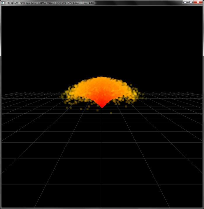
Note that for this demo, we render the particles as points of size 10 units. We could easily change the rendering mode to point sprites with size modified in the vertex shader to give the particles a different look. Also, we can also change the colors and blending modes to achieve various effects. In addition, we could achieve the same result by using one vertex buffer pair with interleaved attributes or two separate transform feedback objects. All of these variants should be straightforward to implement by following the guidelines laid out in this recipe.
We had already looked at a simple approach of simulating GPU-based particle systems using vertex shader in Chapter 5, Mesh Model Formats and Particle Systems, we will now detail pros and cons of each. In Chapter 5 we presented a stateless particle system since all of the attributes (that is, position and velocity) were generated on the fly using the vertex ID, time, and basic kinematic equations on each particle vertex.
As the state of the particle is not stored, we cannot reproduce the same simulation every frame. Hence, collision detection and response are problematic, as we do not have any information of the previous state of the particle, which is often required for collision response. On the contrary, the particle simulation technique presented in this recipe uses a state-preserving particle system. We stored current and previous positions of each particle in buffer objects. In addition, we used transform feedback and a vertex shader for particle simulation on the GPU. As the state of the particle is stored, we can carry out collision detection and response easily.
- OGLDev Tutorial on particle system using transform feedback at http://ogldev.atspace.co.uk/www/tutorial28/tutorial28.html
- OpenGL 4.0 Shading Language Cookbook, Chapter 9, Animation and Particles, the Creating a particle system using transform feedback section, Packt Publishing, 2011.
- Noise based Particles, Part II at The Little Grasshopper, http://prideout.net/blog/?p=67
Chapter8/TransformFeedbackParticles directory.
Let us start this recipe by following these simple steps:
- Set up two vertex array pairs: one for update and another for rendering. Bind two vertex buffer objects to each of the pairs, as was done in the previous two recipes. Here, the buffer objects will store the per-particle properties. Also, enable the corresponding vertex attributes:
glGenVertexArrays(2, vaoUpdateID); glGenVertexArrays(2, vaoRenderID); glGenBuffers( 2, vboID_Pos); glGenBuffers( 2, vboID_PrePos); glGenBuffers( 2, vboID_Direction); for(int i=0;i<2;i++) { glBindVertexArray(vaoUpdateID[i]); glBindBuffer( GL_ARRAY_BUFFER, vboID_Pos[i]); glBufferData( GL_ARRAY_BUFFER, TOTAL_PARTICLES* sizeof(glm::vec4), 0, GL_DYNAMIC_COPY); glEnableVertexAttribArray(0); glVertexAttribPointer(0, 4, GL_FLOAT, GL_FALSE, 0, 0); glBindBuffer( GL_ARRAY_BUFFER, vboID_PrePos[i]); glBufferData( GL_ARRAY_BUFFER, TOTAL_PARTICLES* sizeof(glm::vec4), 0, GL_DYNAMIC_COPY); glEnableVertexAttribArray(1); glVertexAttribPointer(1, 4, GL_FLOAT, GL_FALSE, 0,0); glBindBuffer( GL_ARRAY_BUFFER, vboID_Direction[i]); glBufferData( GL_ARRAY_BUFFER, TOTAL_PARTICLES* sizeof(glm::vec4), 0, GL_DYNAMIC_COPY); glEnableVertexAttribArray(2); glVertexAttribPointer(2, 4, GL_FLOAT, GL_FALSE, 0,0); } for(int i=0;i<2;i++) { glBindVertexArray(vaoRenderID[i]); glBindBuffer( GL_ARRAY_BUFFER, vboID_Pos[i]); glEnableVertexAttribArray(0); glVertexAttribPointer(0, 4, GL_FLOAT, GL_FALSE, 0, 0); }
- Generate a transform feedback object and bind it. Next, specify the output attributes from the shader that would be stored in the transform feedback buffer. After this step, relink the shader program:
glGenTransformFeedbacks(1, &tfID); glBindTransformFeedback(GL_TRANSFORM_FEEDBACK, tfID); const char* varying_names[]={"out_position", "out_prev_position", "out_direction"}; glTransformFeedbackVaryings(particleShader.GetProgram(), 3, varying_names, GL_SEPARATE_ATTRIBS); glLinkProgram(particleShader.GetProgram()); - In the update function, bind the particle vertex shader that will output to the transform feedback buffer and set the appropriate uniforms and update vertex array object. Note that to enable read/write access, we use a pair of vertex array objects such that we can read from one and write to another:
particleShader.Use(); glUniformMatrix4fv(particleShader("MVP"), 1, GL_FALSE, glm::value_ptr(mMVP)); glUniform1f(particleShader("time"), t); for(int i=0;i<NUM_ITER;i++) { glBindVertexArray( vaoUpdateID[readID]); - Bind the vertex buffer objects that will store the outputs from the transform feedback step using the output attributes from the vertex shader:
glBindBufferBase(GL_TRANSFORM_FEEDBACK_BUFFER, 0, vboID_Pos[writeID]); glBindBufferBase(GL_TRANSFORM_FEEDBACK_BUFFER, 1, vboID_PrePos[writeID]); glBindBufferBase(GL_TRANSFORM_FEEDBACK_BUFFER, 2, vboID_Direction[writeID]);
- Disable the rasterizer to prevent the execution of the later stages of the pipeline and then begin the transform feedback. Next, issue a call to the
glDrawArraysfunction to allow the vertices to be passed to the graphics pipeline. After this step, end the transform feedback and then enable the rasterizer. Note that to correctly determine the amount of execution time needed, we issue a hardware query. Next, we alternate the read/write paths by swapping the read and write IDs:glEnable(GL_RASTERIZER_DISCARD); glBeginQuery(GL_TIME_ELAPSED,t_query); glBeginTransformFeedback(GL_POINTS); glDrawArrays(GL_POINTS, 0, TOTAL_PARTICLES); glEndTransformFeedback(); glEndQuery(GL_TIME_ELAPSED); glFlush(); glDisable(GL_RASTERIZER_DISCARD); int tmp = readID; readID=writeID; writeID = tmp;
- Render the particles using the render shader. First, bind the render vertex array object and then draw the points using the
glDrawArraysfunction:glBindVertexArray(vaoRenderID[readID]); renderShader.Use(); glUniformMatrix4fv(renderShader("MVP"), 1, GL_FALSE, glm::value_ptr(mMVP)); glDrawArrays(GL_POINTS, 0, TOTAL_PARTICLES); renderShader.UnUse(); glBindVertexArray(0); - In the particle vertex shader, check if the particle's life is greater than 0. If so, move the particle and reduce the life. Otherwise, calculate a new random direction and reset the life to spawn the particle from the origin. Refer to
Chapter8/TransformFeedbackParticles/shaders/Particle.vertfor details. After this step, output the appropriate values to the output attributes. The particle vertex shader is defined as follows:#version 330 core precision highp float; #extension EXT_gpu_shader4 : require layout( location = 0 ) in vec4 position; layout( location = 1 ) in vec4 prev_position; layout( location = 2 ) in vec4 direction; uniform mat4 MVP; uniform float time; const float PI = 3.14159; const float TWO_PI = 2*PI; const float PI_BY_2 = PI*0.5; const float PI_BY_4 = PI_BY_2*0.5; //shader outputs out vec4 out_position; out vec4 out_prev_position; out vec4 out_direction; const float DAMPING_COEFFICIENT = 0.9995; const vec3 emitterForce = vec3(0.0f,-0.001f, 0.0f); const vec4 collidor = vec4(0,1,0,0); const vec3 emitterPos = vec3(0); float emitterYaw = (0.0f); float emitterYawVar = TWO_PI; float emitterPitch = PI_BY_2; float emitterPitchVar = PI_BY_4; float emitterSpeed = 0.05f; float emitterSpeedVar = 0.01f; int emitterLife = 60; int emitterLifeVar = 15; const float UINT_MAX = 4294967295.0; void main() { vec3 prevPos = prev_position.xyz; int life = int(prev_position.w); vec3 pos = position.xyz; float speed = position.w; vec3 dir = direction.xyz; if(life > 0) { prevPos = pos; pos += dir*speed; if(dot(pos+emitterPos, collidor.xyz)+ collidor.w <0) { dir = reflect(dir, collidor.xyz); speed *= DAMPING_COEFFICIENT; } dir += emitterForce; life--; } else { uint seed = uint(time + gl_VertexID); life = emitterLife + int(randhashf(seed++, emitterLifeVar)); float yaw = emitterYaw + (randhashf(seed++, emitterYawVar )); float pitch = emitterPitch + randhashf(seed++, emitterPitchVar); RotationToDirection(pitch, yaw, dir); float nspeed = emitterSpeed + (randhashf(seed++, emitterSpeedVar )); dir *= nspeed; pos = emitterPos; prevPos = emitterPos; speed = 1; } out_position = vec4(pos, speed); out_prev_position = vec4(prevPos, life); out_direction = vec4(dir, 0); gl_Position = MVP*vec4(pos, 1); }The three helper functions
randhash,randhashf, andRotationToDirectionare defined as follows:uint randhash(uint seed) { uint i=(seed^12345391u)*2654435769u; i^=(i<<6u)^(i>>26u); i*=2654435769u; i+=(i<<5u)^(i>>12u); return i; } float randhashf(uint seed, float b) { return float(b * randhash(seed)) / UINT_MAX; } void RotationToDirection(float pitch, float yaw, out vec3 direction) { direction.x = -sin(yaw) * cos(pitch); direction.y = sin(pitch); direction.z = cos(pitch) * cos(yaw); }
The transform feedback mechanism allows us to feedback one or more attributes from the vertex shader or geometry shader back to a buffer object. This feedback path could be used for implementing a physically-based simulation. This recipe uses this mechanism to output the particle position after each iteration. After each step, the buffers are swapped and, therefore, it can simulate the particle motion.
To make the particle system, we first set up three pairs of vertex buffer objects that store the per-particle attributes that we input to the vertex shader. These include the particle's position, previous position, life, direction, and speed. These are stored into separate buffer objects for convenience. We could have stored all of these attributes into a single interleaved buffer object. Since we output to the buffer object from our shader, we specify the buffer object usage as GL_DYNAMIC_COPY. Similarly, we set up a separate vertex array object for rendering the particles:
Next, we specify the shader output attributes that we would like to connect to the transform feedback buffers. We use three outputs, namely out_position, out_prev_position, and out_direction, which output the particle's current position, particle's previous position, and the particle's direction along with the particle's speed, current, and initial life, respectively. We specify that we would connect these to separate buffer objects:
We then run a loop for the number of iterations desired. In the loop, we first bind the update vertex array object and assign the appropriate transform feedback buffer base indices:
If the life is less than 0, we reset the particle's direction of motion to a new random direction. We reset the life to a random value based on the maximum allowed value. The current and previous positions of the particle are reset to the emitter origin and finally, the speed is reset to the default value. We then output the output attributes:
Note that for this demo, we render the particles as points of size 10 units. We could easily change the rendering mode to point sprites with size modified in the vertex shader to give the particles a different look. Also, we can also change the colors and blending modes to achieve various effects. In addition, we could achieve the same result by using one vertex buffer pair with interleaved attributes or two separate transform feedback objects. All of these variants should be straightforward to implement by following the guidelines laid out in this recipe.
We had already looked at a simple approach of simulating GPU-based particle systems using vertex shader in Chapter 5, Mesh Model Formats and Particle Systems, we will now detail pros and cons of each. In Chapter 5 we presented a stateless particle system since all of the attributes (that is, position and velocity) were generated on the fly using the vertex ID, time, and basic kinematic equations on each particle vertex.
As the state of the particle is not stored, we cannot reproduce the same simulation every frame. Hence, collision detection and response are problematic, as we do not have any information of the previous state of the particle, which is often required for collision response. On the contrary, the particle simulation technique presented in this recipe uses a state-preserving particle system. We stored current and previous positions of each particle in buffer objects. In addition, we used transform feedback and a vertex shader for particle simulation on the GPU. As the state of the particle is stored, we can carry out collision detection and response easily.
- OGLDev Tutorial on particle system using transform feedback at http://ogldev.atspace.co.uk/www/tutorial28/tutorial28.html
- OpenGL 4.0 Shading Language Cookbook, Chapter 9, Animation and Particles, the Creating a particle system using transform feedback section, Packt Publishing, 2011.
- Noise based Particles, Part II at The Little Grasshopper, http://prideout.net/blog/?p=67
recipe by following these simple steps:
- Set up two vertex array pairs: one for update and another for rendering. Bind two vertex buffer objects to each of the pairs, as was done in the previous two recipes. Here, the buffer objects will store the per-particle properties. Also, enable the corresponding vertex attributes:
glGenVertexArrays(2, vaoUpdateID); glGenVertexArrays(2, vaoRenderID); glGenBuffers( 2, vboID_Pos); glGenBuffers( 2, vboID_PrePos); glGenBuffers( 2, vboID_Direction); for(int i=0;i<2;i++) { glBindVertexArray(vaoUpdateID[i]); glBindBuffer( GL_ARRAY_BUFFER, vboID_Pos[i]); glBufferData( GL_ARRAY_BUFFER, TOTAL_PARTICLES* sizeof(glm::vec4), 0, GL_DYNAMIC_COPY); glEnableVertexAttribArray(0); glVertexAttribPointer(0, 4, GL_FLOAT, GL_FALSE, 0, 0); glBindBuffer( GL_ARRAY_BUFFER, vboID_PrePos[i]); glBufferData( GL_ARRAY_BUFFER, TOTAL_PARTICLES* sizeof(glm::vec4), 0, GL_DYNAMIC_COPY); glEnableVertexAttribArray(1); glVertexAttribPointer(1, 4, GL_FLOAT, GL_FALSE, 0,0); glBindBuffer( GL_ARRAY_BUFFER, vboID_Direction[i]); glBufferData( GL_ARRAY_BUFFER, TOTAL_PARTICLES* sizeof(glm::vec4), 0, GL_DYNAMIC_COPY); glEnableVertexAttribArray(2); glVertexAttribPointer(2, 4, GL_FLOAT, GL_FALSE, 0,0); } for(int i=0;i<2;i++) { glBindVertexArray(vaoRenderID[i]); glBindBuffer( GL_ARRAY_BUFFER, vboID_Pos[i]); glEnableVertexAttribArray(0); glVertexAttribPointer(0, 4, GL_FLOAT, GL_FALSE, 0, 0); }
- Generate a transform feedback object and bind it. Next, specify the output attributes from the shader that would be stored in the transform feedback buffer. After this step, relink the shader program:
glGenTransformFeedbacks(1, &tfID); glBindTransformFeedback(GL_TRANSFORM_FEEDBACK, tfID); const char* varying_names[]={"out_position", "out_prev_position", "out_direction"}; glTransformFeedbackVaryings(particleShader.GetProgram(), 3, varying_names, GL_SEPARATE_ATTRIBS); glLinkProgram(particleShader.GetProgram()); - In the update function, bind the particle vertex shader that will output to the transform feedback buffer and set the appropriate uniforms and update vertex array object. Note that to enable read/write access, we use a pair of vertex array objects such that we can read from one and write to another:
particleShader.Use(); glUniformMatrix4fv(particleShader("MVP"), 1, GL_FALSE, glm::value_ptr(mMVP)); glUniform1f(particleShader("time"), t); for(int i=0;i<NUM_ITER;i++) { glBindVertexArray( vaoUpdateID[readID]); - Bind the vertex buffer objects that will store the outputs from the transform feedback step using the output attributes from the vertex shader:
glBindBufferBase(GL_TRANSFORM_FEEDBACK_BUFFER, 0, vboID_Pos[writeID]); glBindBufferBase(GL_TRANSFORM_FEEDBACK_BUFFER, 1, vboID_PrePos[writeID]); glBindBufferBase(GL_TRANSFORM_FEEDBACK_BUFFER, 2, vboID_Direction[writeID]);
- Disable the rasterizer to prevent the execution of the later stages of the pipeline and then begin the transform feedback. Next, issue a call to the
glDrawArraysfunction to allow the vertices to be passed to the graphics pipeline. After this step, end the transform feedback and then enable the rasterizer. Note that to correctly determine the amount of execution time needed, we issue a hardware query. Next, we alternate the read/write paths by swapping the read and write IDs:glEnable(GL_RASTERIZER_DISCARD); glBeginQuery(GL_TIME_ELAPSED,t_query); glBeginTransformFeedback(GL_POINTS); glDrawArrays(GL_POINTS, 0, TOTAL_PARTICLES); glEndTransformFeedback(); glEndQuery(GL_TIME_ELAPSED); glFlush(); glDisable(GL_RASTERIZER_DISCARD); int tmp = readID; readID=writeID; writeID = tmp;
- Render the particles using the render shader. First, bind the render vertex array object and then draw the points using the
glDrawArraysfunction:glBindVertexArray(vaoRenderID[readID]); renderShader.Use(); glUniformMatrix4fv(renderShader("MVP"), 1, GL_FALSE, glm::value_ptr(mMVP)); glDrawArrays(GL_POINTS, 0, TOTAL_PARTICLES); renderShader.UnUse(); glBindVertexArray(0); - In the particle vertex shader, check if the particle's life is greater than 0. If so, move the particle and reduce the life. Otherwise, calculate a new random direction and reset the life to spawn the particle from the origin. Refer to
Chapter8/TransformFeedbackParticles/shaders/Particle.vertfor details. After this step, output the appropriate values to the output attributes. The particle vertex shader is defined as follows:#version 330 core precision highp float; #extension EXT_gpu_shader4 : require layout( location = 0 ) in vec4 position; layout( location = 1 ) in vec4 prev_position; layout( location = 2 ) in vec4 direction; uniform mat4 MVP; uniform float time; const float PI = 3.14159; const float TWO_PI = 2*PI; const float PI_BY_2 = PI*0.5; const float PI_BY_4 = PI_BY_2*0.5; //shader outputs out vec4 out_position; out vec4 out_prev_position; out vec4 out_direction; const float DAMPING_COEFFICIENT = 0.9995; const vec3 emitterForce = vec3(0.0f,-0.001f, 0.0f); const vec4 collidor = vec4(0,1,0,0); const vec3 emitterPos = vec3(0); float emitterYaw = (0.0f); float emitterYawVar = TWO_PI; float emitterPitch = PI_BY_2; float emitterPitchVar = PI_BY_4; float emitterSpeed = 0.05f; float emitterSpeedVar = 0.01f; int emitterLife = 60; int emitterLifeVar = 15; const float UINT_MAX = 4294967295.0; void main() { vec3 prevPos = prev_position.xyz; int life = int(prev_position.w); vec3 pos = position.xyz; float speed = position.w; vec3 dir = direction.xyz; if(life > 0) { prevPos = pos; pos += dir*speed; if(dot(pos+emitterPos, collidor.xyz)+ collidor.w <0) { dir = reflect(dir, collidor.xyz); speed *= DAMPING_COEFFICIENT; } dir += emitterForce; life--; } else { uint seed = uint(time + gl_VertexID); life = emitterLife + int(randhashf(seed++, emitterLifeVar)); float yaw = emitterYaw + (randhashf(seed++, emitterYawVar )); float pitch = emitterPitch + randhashf(seed++, emitterPitchVar); RotationToDirection(pitch, yaw, dir); float nspeed = emitterSpeed + (randhashf(seed++, emitterSpeedVar )); dir *= nspeed; pos = emitterPos; prevPos = emitterPos; speed = 1; } out_position = vec4(pos, speed); out_prev_position = vec4(prevPos, life); out_direction = vec4(dir, 0); gl_Position = MVP*vec4(pos, 1); }The three helper functions
randhash,randhashf, andRotationToDirectionare defined as follows:uint randhash(uint seed) { uint i=(seed^12345391u)*2654435769u; i^=(i<<6u)^(i>>26u); i*=2654435769u; i+=(i<<5u)^(i>>12u); return i; } float randhashf(uint seed, float b) { return float(b * randhash(seed)) / UINT_MAX; } void RotationToDirection(float pitch, float yaw, out vec3 direction) { direction.x = -sin(yaw) * cos(pitch); direction.y = sin(pitch); direction.z = cos(pitch) * cos(yaw); }
The transform feedback mechanism allows us to feedback one or more attributes from the vertex shader or geometry shader back to a buffer object. This feedback path could be used for implementing a physically-based simulation. This recipe uses this mechanism to output the particle position after each iteration. After each step, the buffers are swapped and, therefore, it can simulate the particle motion.
To make the particle system, we first set up three pairs of vertex buffer objects that store the per-particle attributes that we input to the vertex shader. These include the particle's position, previous position, life, direction, and speed. These are stored into separate buffer objects for convenience. We could have stored all of these attributes into a single interleaved buffer object. Since we output to the buffer object from our shader, we specify the buffer object usage as GL_DYNAMIC_COPY. Similarly, we set up a separate vertex array object for rendering the particles:
Next, we specify the shader output attributes that we would like to connect to the transform feedback buffers. We use three outputs, namely out_position, out_prev_position, and out_direction, which output the particle's current position, particle's previous position, and the particle's direction along with the particle's speed, current, and initial life, respectively. We specify that we would connect these to separate buffer objects:
We then run a loop for the number of iterations desired. In the loop, we first bind the update vertex array object and assign the appropriate transform feedback buffer base indices:
If the life is less than 0, we reset the particle's direction of motion to a new random direction. We reset the life to a random value based on the maximum allowed value. The current and previous positions of the particle are reset to the emitter origin and finally, the speed is reset to the default value. We then output the output attributes:
Note that for this demo, we render the particles as points of size 10 units. We could easily change the rendering mode to point sprites with size modified in the vertex shader to give the particles a different look. Also, we can also change the colors and blending modes to achieve various effects. In addition, we could achieve the same result by using one vertex buffer pair with interleaved attributes or two separate transform feedback objects. All of these variants should be straightforward to implement by following the guidelines laid out in this recipe.
We had already looked at a simple approach of simulating GPU-based particle systems using vertex shader in Chapter 5, Mesh Model Formats and Particle Systems, we will now detail pros and cons of each. In Chapter 5 we presented a stateless particle system since all of the attributes (that is, position and velocity) were generated on the fly using the vertex ID, time, and basic kinematic equations on each particle vertex.
As the state of the particle is not stored, we cannot reproduce the same simulation every frame. Hence, collision detection and response are problematic, as we do not have any information of the previous state of the particle, which is often required for collision response. On the contrary, the particle simulation technique presented in this recipe uses a state-preserving particle system. We stored current and previous positions of each particle in buffer objects. In addition, we used transform feedback and a vertex shader for particle simulation on the GPU. As the state of the particle is stored, we can carry out collision detection and response easily.
- OGLDev Tutorial on particle system using transform feedback at http://ogldev.atspace.co.uk/www/tutorial28/tutorial28.html
- OpenGL 4.0 Shading Language Cookbook, Chapter 9, Animation and Particles, the Creating a particle system using transform feedback section, Packt Publishing, 2011.
- Noise based Particles, Part II at The Little Grasshopper, http://prideout.net/blog/?p=67
feedback mechanism allows us to feedback one or more attributes from the vertex shader or geometry shader back to a buffer object. This feedback path could be used for implementing a physically-based simulation. This recipe uses this mechanism to output the particle position after each iteration. After each step, the buffers are swapped and, therefore, it can simulate the particle motion.
To make the particle system, we first set up three pairs of vertex buffer objects that store the per-particle attributes that we input to the vertex shader. These include the particle's position, previous position, life, direction, and speed. These are stored into separate buffer objects for convenience. We could have stored all of these attributes into a single interleaved buffer object. Since we output to the buffer object from our shader, we specify the buffer object usage as GL_DYNAMIC_COPY. Similarly, we set up a separate vertex array object for rendering the particles:
Next, we specify the shader output attributes that we would like to connect to the transform feedback buffers. We use three outputs, namely out_position, out_prev_position, and out_direction, which output the particle's current position, particle's previous position, and the particle's direction along with the particle's speed, current, and initial life, respectively. We specify that we would connect these to separate buffer objects:
We then run a loop for the number of iterations desired. In the loop, we first bind the update vertex array object and assign the appropriate transform feedback buffer base indices:
If the life is less than 0, we reset the particle's direction of motion to a new random direction. We reset the life to a random value based on the maximum allowed value. The current and previous positions of the particle are reset to the emitter origin and finally, the speed is reset to the default value. We then output the output attributes:
Note that for this demo, we render the particles as points of size 10 units. We could easily change the rendering mode to point sprites with size modified in the vertex shader to give the particles a different look. Also, we can also change the colors and blending modes to achieve various effects. In addition, we could achieve the same result by using one vertex buffer pair with interleaved attributes or two separate transform feedback objects. All of these variants should be straightforward to implement by following the guidelines laid out in this recipe.
We had already looked at a simple approach of simulating GPU-based particle systems using vertex shader in Chapter 5, Mesh Model Formats and Particle Systems, we will now detail pros and cons of each. In Chapter 5 we presented a stateless particle system since all of the attributes (that is, position and velocity) were generated on the fly using the vertex ID, time, and basic kinematic equations on each particle vertex.
As the state of the particle is not stored, we cannot reproduce the same simulation every frame. Hence, collision detection and response are problematic, as we do not have any information of the previous state of the particle, which is often required for collision response. On the contrary, the particle simulation technique presented in this recipe uses a state-preserving particle system. We stored current and previous positions of each particle in buffer objects. In addition, we used transform feedback and a vertex shader for particle simulation on the GPU. As the state of the particle is stored, we can carry out collision detection and response easily.
- OGLDev Tutorial on particle system using transform feedback at http://ogldev.atspace.co.uk/www/tutorial28/tutorial28.html
- OpenGL 4.0 Shading Language Cookbook, Chapter 9, Animation and Particles, the Creating a particle system using transform feedback section, Packt Publishing, 2011.
- Noise based Particles, Part II at The Little Grasshopper, http://prideout.net/blog/?p=67
with interleaved attributes or two separate transform feedback objects. All of these variants should be straightforward to implement by following the guidelines laid out in this recipe.
We had already looked at a simple approach of simulating GPU-based particle systems using vertex shader in Chapter 5, Mesh Model Formats and Particle Systems, we will now detail pros and cons of each. In Chapter 5 we presented a stateless particle system since all of the attributes (that is, position and velocity) were generated on the fly using the vertex ID, time, and basic kinematic equations on each particle vertex.
As the state of the particle is not stored, we cannot reproduce the same simulation every frame. Hence, collision detection and response are problematic, as we do not have any information of the previous state of the particle, which is often required for collision response. On the contrary, the particle simulation technique presented in this recipe uses a state-preserving particle system. We stored current and previous positions of each particle in buffer objects. In addition, we used transform feedback and a vertex shader for particle simulation on the GPU. As the state of the particle is stored, we can carry out collision detection and response easily.
- OGLDev Tutorial on particle system using transform feedback at http://ogldev.atspace.co.uk/www/tutorial28/tutorial28.html
- OpenGL 4.0 Shading Language Cookbook, Chapter 9, Animation and Particles, the Creating a particle system using transform feedback section, Packt Publishing, 2011.
- Noise based Particles, Part II at The Little Grasshopper, http://prideout.net/blog/?p=67
- http://ogldev.atspace.co.uk/www/tutorial28/tutorial28.html
- OpenGL 4.0 Shading Language Cookbook, Chapter 9, Animation and Particles, the Creating a particle system using transform feedback section, Packt Publishing, 2011.
- Noise based Particles, Part II at The Little Grasshopper, http://prideout.net/blog/?p=67