
Understanding parametric modelling
Parametric modeling is the core principle that SOLIDWORKS operates on. It governs how SOLIDWORKS constructs 3D models and how a user should think when dealing with SOLIDWORKS.
In parametric modeling, the model is created based on relationships and a set of logical arrangements that are set by the designer or draftsman. In the SOLIDWORKS software environment, they are represented by dimensions, geometric relationships, and features that link different parts of a model to each other. Each of these logical features is called a parameter.
For example, a simple cube with a side length of 1 mm would contain the following parameters:
- Four lines in one plane with the following relationships listed and noted in the following diagram in writing:
- All two-line endpoints are merged at the same point. This is presented with the merged parameter in the following diagram.
- Two opposite angles are right angles (90 degrees).
- Two adjacent lines are equal to each other in length.
- The length of one line is 1 mm, as follows:
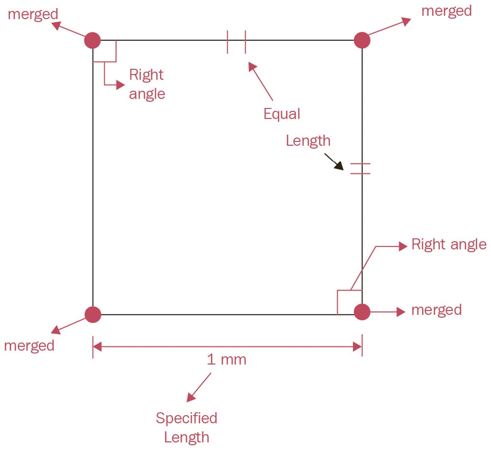
Figure 1.6 – Four lines in one plane
- A Vertical Extrusion that is perpendicular to the square defined in the first set of parameters. This extrusion is by an amount equal to the length of the square's side (1 mm). This vertical extrusion will result in the shape shown in the following diagram:
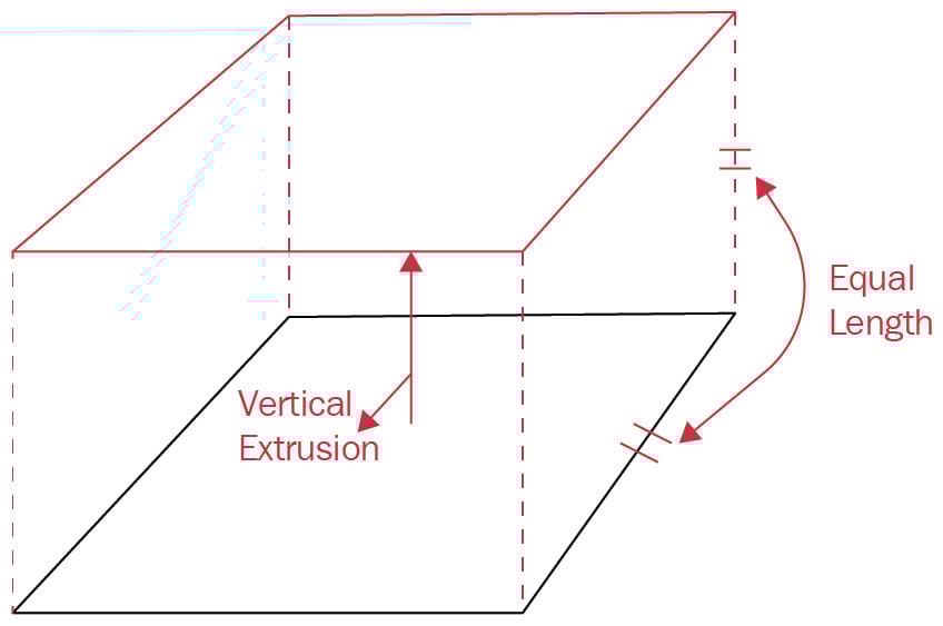
Figure 1.7 – Extruding four base lines upward to make a cube
The parameters listed here show how software such as SOLIDWORKS interprets and constructs 3D models. Another term that is commonly used to refer to those parameters is design intent. The user of the software should specify all those parameters to create a cube or any other 3D model. Creating 3D models based on parameters/design settings has many notable advantages. One major advantage is the ease of applying design updates. Let's go back to our cube to see how this works.
Notice that in the preceding cube, we have specified the length of only one side in the base square; the other specifications are all relationships that fix and highlight the fact that the model is a cube (equal, parallel, and perpendicular sides). Those parameters make all the parts of our cube inter-connected based on what we decide is important. Thus, updating the length of the side of the cube will not sabotage the cube's structure. Rather, the whole cube will be updated while keeping the parameters intact.
To clarify this, we can revisit the cube we just made to update it. In the same model, let's change the dimension we identified earlier from 1 mm to 5 mm:
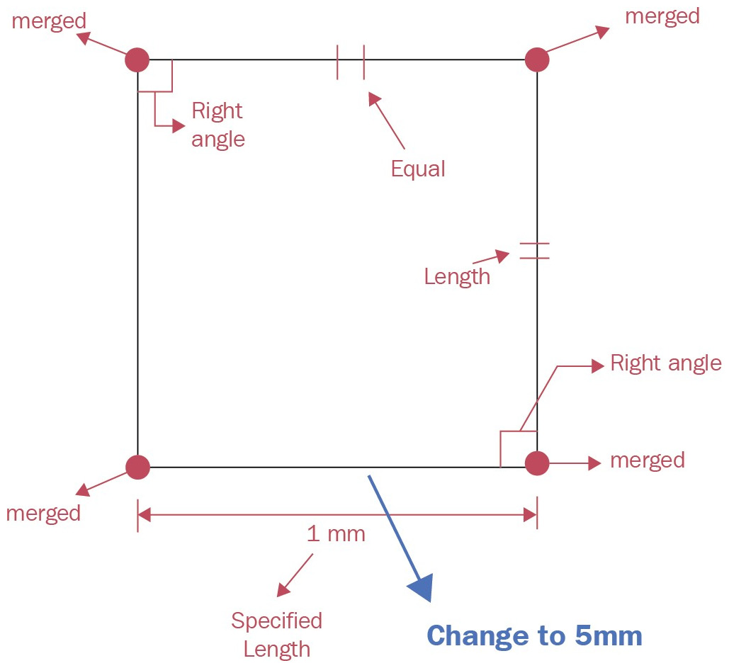
Figure 1.8 – Adjusting the elements in a parametric design propagated to the different parts
With that single step, the cube is fully modified, with all the sides changing to 5 mm in length. Again, this is because our cube parameters must have equal perpendicular and parallel sides. Given that we have defined our intended parameters/design settings for the software, all of those will be retained, resulting in the whole cube model being updated with one single adjustment.
This can be contrasted with pure direct modeling methods. In pure direct modeling, the user creates the cube more abstractly by drawing each line separately and constructing a cube of a certain size. Even though creating the initial cube might be faster, updating it would require updating all of the elements separately as they don't relate to each other with any intent or logical features. This would result in considerably more time and effort being invested in creating variations, which is an essential requirement for industrial applications.
Other advantages of parametric modeling are as follows:
- The ease of modifying and adjusting models throughout the design and production cycles.
- The ease of creating families of parts that have similar parameters.
- The ease of communicating the design to manufacturing establishments for manufacturing.
All the advantages of parametric modeling make it a popular modeling method for technical applications relating to engineering or product design. On the other hand, direct modeling can perform better in more abstract applications, such as modeling more artistic objects used in gaming or architecture. Understanding parametric modeling will enable us to use the software more easily as we are aware of its limitations, as well as how the software interprets the commands we apply. As we go through this book, we will expand our understanding of parametric modeling as we tackle more advanced functions, such as design tables and other features.
Now that we know more about SOLIDWORKS and parametric modeling, we will discuss the certifications offered by SOLIDWORKS.