
Overview of SOLIDWORKS simulation
This section introduces the SOLIDWORKS Simulation, highlights the basic steps required for most simulations, discusses the type of finite elements provided by SOLIDWORKS Simulation, and covers the SOLIDWORKS Simulation license, its computing requirements, and its limitations.
What is SOLIDWORKS Simulation?
SOLIDWORKS Simulation is the implementation of the FEM in the SOLIDWORKS CAD environment by SOLIDWORKS Corporation (whose parent company, Dassault Systèmes, makes the SOLIDWORKS CAD software). The SOLIDWORKS CAD software has a reputation for being user-friendly, and it is clearly a leader in the 3D design modeling market.
Riding on the wave of popularity of SOLIDWORKS as a design modeling tool, SOLIDWORKS Simulation was developed in the same spirit to provide an easy, one-stop platform for design analyses. In addition to this, SOLIDWORKS Simulation is established on the backbone of fast numerical solvers. It simplifies the workflow for obtaining a detailed solution for stress, thermal, frequency, flow, transient, buckling, pressure vessels, and optimization analyses, among others. Fully embedded within the SOLIDWORKS environment, SOLIDWORKS Simulation helps product designers to do the following:
- Reduce the cost of prototyping by facilitating a virtual testing platform in place of costly early-stage physical tests.
- Shorten the concept-to-product timeframe and the time to market.
- Accelerate the analysis of design iterations.
- Evaluate the optimal design with parametric analyses.
- Analyze complex parts and assemblies with support for different material behavior (such as linear or nonlinear).
- Conduct simulation on subassemblies with support for contact and interaction involving machine elements such as bolts, pins, springs, and bearings.
Basic steps in SOLIDWORKS Simulation
In this section, we will highlight the steps required for the analyses of a single-member component and a multi-member assembly using SOLIDWORKS Simulation. The steps are summarized in Figure 1.1 and Figure 1.2, representing the expansion of the phases in FEA that were briefly mentioned in the Implementations of FEA section :
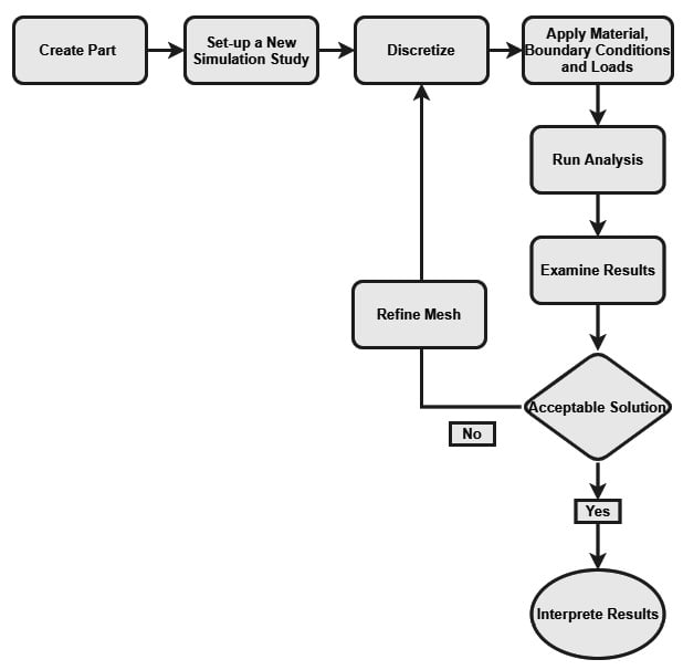
Figure 1.1 – Flowchart for the static analysis of a one-member component
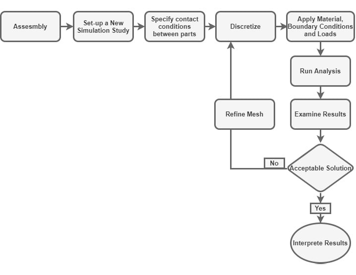
Figure 1.2 – Flowchart for the static analysis of an assembly
A couple of comments regarding the steps indicated in Figure 1.1 and Figure 1.2 are provided as follows:
- The first step to the simulation of a product (such as a part or an assembly) is to create its CAD model. At this stage, all geometric properties are defined. For complicated geometries, the geometry of the structure to be analyzed might have to be defeatured and fine-tuned.
- Next, the SOLIDWORKS Simulation interface is launched.
- Discretization of the part or assembly is carried out. Often, discretization is called meshing. This refers to the crucial process of dividing a part or assembly into smaller pieces (similar to LEGO pieces). A few concepts need to be known regarding meshing:
- Meshing creates elements and nodes.
- An element describes a finite-sized division created from the original component to be analyzed.
- Elements are joined by common points called nodes.
- Each finite element is characterized by a specific number of degrees of freedom. A degree of freedom is the fundamental field variable calculated during the FEA. For instance, for static analysis problems, the displacement vector is the main degree of freedom during the computation. However, in the case of simulations related to thermal analysis problems, the degree of freedom is temperature.
- The size and type of elements created during meshing are key to getting accurate results. Typically, the types of elements to be used for analysis become obvious from the nature of the problem. This concept will be developed further throughout the book.
- After the discretization step, we will specify the following:
- Material properties. For static analysis, this will generally include stiffness information such as Young's modulus and Poisson's ratio.
- Loads. A variety of loads can be applied within the SOLIDWORKS Simulation interface, ranging from axial load, transverse load, torsional load to pressure load.
- Fixtures. In the language of SOLIDWORKS Simulation, the word "fixture" is used to indicate boundary conditions. Meanwhile, boundary conditions generally refer to physical constraints on the movement of specific joints or segments of a load-bearing structure. They arise from the presence of supports used to ensure that a structure being analyzed is properly constrained to prevent rigid body motion during the application of external loads.
- Connections. In the language of SOLIDWORKS Simulation, the connections settings comprise the contact condition that is required anytime two or more components touch each other before or during the simulation process. This might arise from welding, bonding, riveting, or various other types of joining of a practical nature. SOLIDWORKS Simulation provides a variety of contact types that will be explored as we progress in our exploration of the software.
- Finally, we run the analysis, then obtain and interpret the results.
Information
In FEA, elements of different shapes, degrees of freedom (DOF), and complexity exist. In principle, when the term DOF is used in mechanics, it denotes the number of independent quantities required to describe a displaced or perturbed state of a structure. For static problems that are the focus of this book, we will be using DOF to refer to the number of possible displacement components at nodes of a specific finite element. Note that a comprehensive account of the mathematical derivations for a wide variety of elements is not addressed in this book. Such derivations can be found in many of the books on the mathematical foundation of the FEM such as [3] and [4].
Elements within SOLIDWORKS Simulation
SOLIDWORKS Simulation has three major families of elements that are used in the performance analysis of components:
- Continuum elements:
- Solid elements
- Two-dimensional (2D) plane elements
- Structural elements:
- Beam elements
- Truss elements
- Shell elements
- Special elements
While these elements will be rigorously explored in subsequent chapters, Table 1-2 highlights three representative cases of when to use these elements.
Generally, a solid element is used for bulky models with considerable thickness and volume. 2D plane elements are employed for the 2D analysis of members (such as axisymmetric, plane stress, or plane strain problems). Beam and truss elements are used for the analysis of structural members that have one of their dimensions far greater than the dimensions of their cross-sections. Shell elements are deployed for thin-walled members. The special elements mostly connect elements such as springs elastic supports, and more:
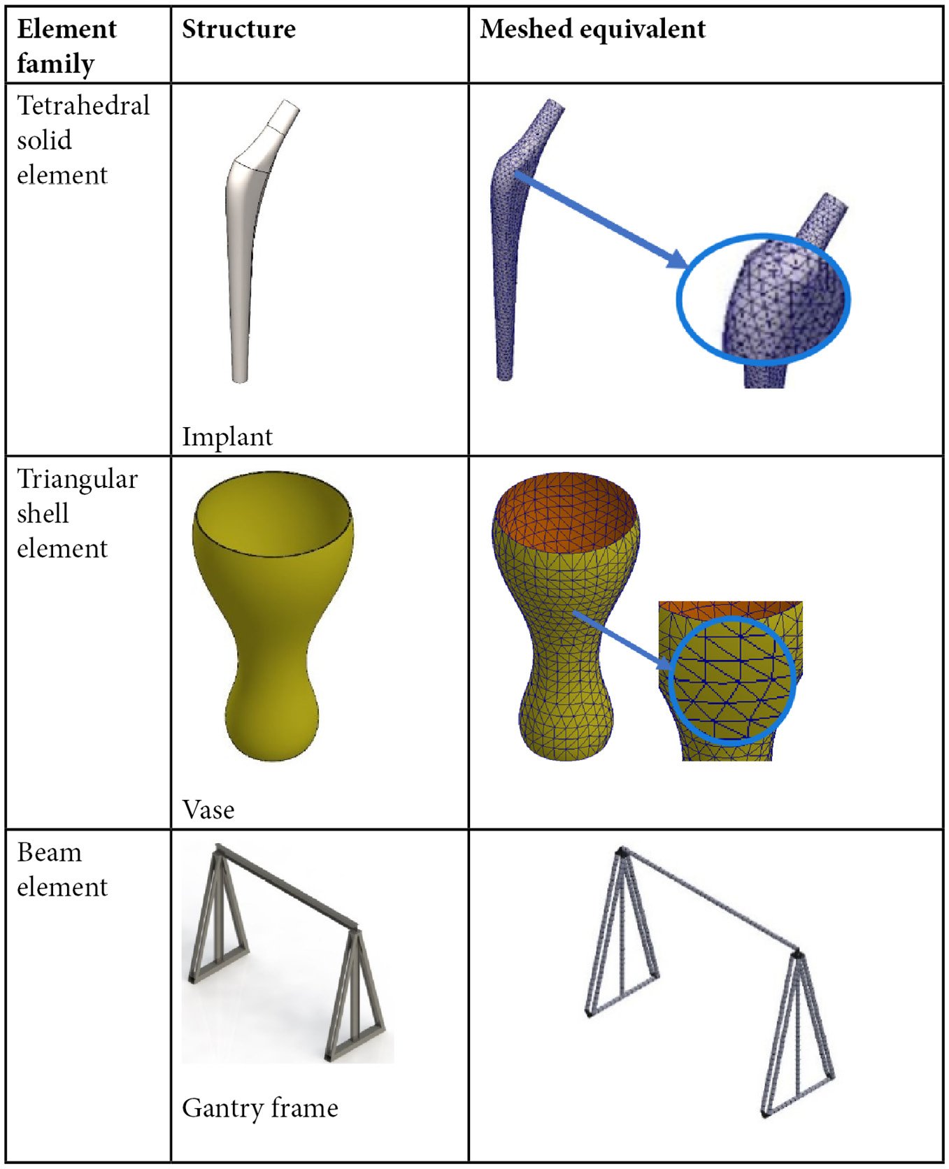
Table 1-2: Discretization and the major types of elements
Types of SOLIDWORKS Simulation license
SOLIDWORKS Corporation offers three types of license for SOLIDWORKS Simulation:
- SOLIDWORKS Simulation Standard
- SOLIDWORKS Simulation Professional
- SOLIDWORKS Simulation Premium
Of these three, the premium license is the most comprehensive in terms of capability. The professional license does not support nonlinear and composite analyses. The standard license is even more limited in terms of the scope of analyses it supports. For this book, the premium license is employed.
Information
To read more about the kinds of analyses that can be carried out with each of the previously mentioned licenses, please visit https://www.solidworks.com/product/solidworks-simulation.
Computing requirements
SOLIDWORKS is a memory-hungry application. This is understandable given the functionalities that are packed into this amazing piece of software. For best performance, the recommendation listed in Table 1-3 is suggested for PCs or laptops to be used for basic analysis with the SOLIDWORKS Simulation:
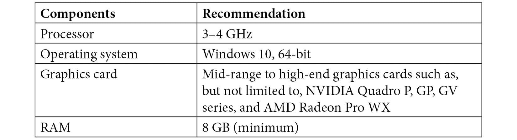
Table 1-3: System requirements
Information
For further information about system requirements, beyond the details in Table 1-3, head over to https://www.solidworks.com/support/system-requirements.
What are the limitations of SOLIDWORKS Simulation?
While SOLIDWORKS Simulation is a powerful tool that can be used for numerous kinds of analyses of products and components, it is worth mentioning that it has a limited number of elements in its library. This point should be borne in mind while dealing with multiphysics problems for which a suitable element for the analysis might not exist in the SOLIDWORKS Simulation library. Besides, you should always find alternative methods to determine the accuracy of the results retrieved from the SOLIDWORKS Simulation. This is known as validation, and it can be done via experiments or analytical techniques at one stage of the product development phases. The approach to such methods of validation through experimental stress techniques is not covered in this book (a classic reference is a text by Dally and Riley [5]).
This wraps up our presentation of the overview of the SOLIDWORKS Simulation. In the next section, we will do a cursory examination of the SOLIDWORKS interfaces.