

Automatically highlighting unglued connectors
The Dynamic connector master can be enhanced to be displayed as a red dashed line, for example, if it is not connected at both ends.
Again, we must edit the Dynamic connector master in local Document Stencil and consider the LinePattern and LineColor cells in the Line Format section and the BegTrigger and EndTrigger cells in the Glue Info section, as in the following screenshot:
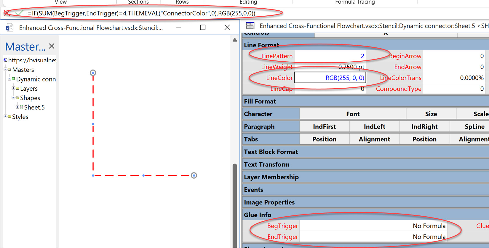
Figure 11.15 – Show unconnected lines with a red dash
It is possible to check whether the connector is connected at both ends by checking that the formulas that will be automatically assigned by Visio to the BegTrigger and EndTrigger cells each evaluate to 2.
The default formula for the LinePattern cell is as follows:
=THEMEVAL("ConnectorPattern")
Visio has an ID number for each of the built-in patterns, which you can see on the Format Shape panel. So, if we want it to be dashed, which is ID = 2, we can...