
When considering the private cloud, traditionally, company's private datacenters have implemented 3-tier layer 2 networks based on the Spanning Tree Protocol (STP), which doesn't lend itself well to modern software-defined networks. So, we will look at what a STP is in more depth as well as modern Leaf-Spine network architectures.
The implementation of STP provides a number of options for network architects in terms of implementation, but it also adds a layer of complexity to the network. Implementation of the STP gives network architects the certainty that it will prevent layer 2 loops from occurring in the network.
A typical representation of a 3-tier layer 2 STP-based network can be shown as follows:
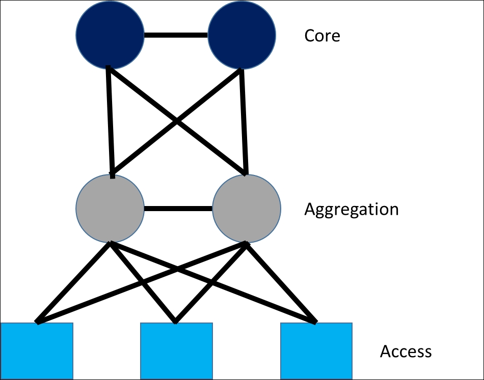
The Core layer provides routing services to other parts of the data center and contains the core switches
The Aggregation layer provides connectivity to adjacent Access layer switches and the top of the Spanning Tree core
The bottom of the tree is the Access layer; this is where bare metal (physical) or virtual machines connect to the network and are segmented using different VLANs.
The use of layer 2 networking and STP mean that at the access layer of the network will use VLANs spread throughout the network. The VLANs sit at the access layer, which is where virtual machines or bare metal servers are connected. Typically, these VLANs are grouped by type of application, and firewalls are used to further isolate and secure them.
Traditional networks are normally segregated into some combination of the following:
Frontend: It typically has web servers that require external access
Business Logic: This often contains stateful services
Backend: This typically contains database servers
Applications communicate with each other by tunneling between these firewalls, with specific Access Control List (ACL) rules that are serviced by network teams and governed by security teams.
When using STP in a layer 2 network, all switches go through an election process to determine the root switch, which is granted to the switch with the lowest bridge id, with a bridge id encompassing the bridge priority and MAC address of the switch.
Once elected, the root switch becomes the base of the spanning tree; all other switches in the Spanning Tree are deemed non-root will calculate their shortest path to the root and then block any redundant links, so there is one clear path. The calculation process to work out the shortest path is referred to as network convergence. (For more information refer to the following link: http://etutorials.org/Networking/Lan+switching+fundamentals/Chapter+10.+Implementing+and+Tuning+Spanning+Tree/Spanning-Tree+Convergence/)
Network architects designing the layer 2 Spanning Tree network need to be careful about the placement of the root switch, as all network traffic will need to flow through it, so it should be selected with care and given an appropriate bridge priority as part of the network reference architecture design. If at any point, switches have been given the same bridge priority then the bridge with the lowest MAC address wins.
Network architects should also design the network for redundancy so that if a root switch fails, there is a nominated backup root switch with a priority of one value less than the nominated root switch, which will take over when a root switch fails. In the scenario, the root switch fails the election process will begin again and the network will converge, which can take some time.
The use of STP is not without its risks, if it does fail due to user configuration error, data center equipment failure or software failure on a switch or bad design, then the consequences to a network can be huge. The result can be that loops might form within the bridged network, which can result in a flood of broadcast, multicast or unknown-unicast storms that can potentially take down the entire network leading to long network outages. The complexity associated with network architects or engineers troubleshooting STP issues is important, so it is paramount that the network design is sound.
In recent years with the emergence of cloud computing, we have seen data centers move away from a STP in favor of a Leaf-Spine networking architecture. The Leaf-Spine architecture is shown in the following diagram:

In a Leaf-Spine architecture:
Spine switches are connected into a set of core switches
Spine switches are then connected with Leaf switches with each Leaf switch deployed at the top of rack, which means that any Leaf switch can connect to any Spine switch in one hop
Leaf-Spine architectures are promoted by companies such as Arista, Juniper, and Cisco. A Leaf-Spine architecture is built on layer 3 routing principle to optimize throughput and reduce latency.
Both Leaf and Spine switches communicate with each other via external Border Gate Protocol (eBGP) as the routing protocol for the IP fabric. eBGP establishes a Transmission Control Protocol (TCP) connection to each of its BGP peers before BGP updates can be exchanged between the switches. Leaf switches in the implementation will sit at top of rack and can be configured in Multichassis Link Aggregation (MLAG) mode using Network Interface Controller (NIC) bonding.
MLAG was originally used with STP so that two or more switches are bonded to emulate like a single switch and used for redundancy so they appeared as one switch to STP. In the event of a failure this provided multiple uplinks for redundancy in the event of a failure as the switches are peered, and it worked around the need to disable redundant paths. Leaf switches can often have internal Border Gate Protocol (iBGP) configured between the pairs of switches for resiliency.
In a Leaf-Spine architecture, Spine switches do not connect to other Spine switches, and Leaf switches do not connect directly to other Leaf switches unless bonded top of rack using MLAG NIC bonding. All links in a Leaf-Spine architecture are set up to forward with no looping. Leaf-Spine architectures are typically configured to implement Equal Cost Multipathing (ECMP), which allows all routes to be configured on the switches so that they can access any Spine switch in the layer 3 routing fabric.
ECMP means that Leaf switches routing table has the next-hop configured to forward to each Spine switch. In an ECMP setup, each leaf node has multiple paths of equal distance to each Spine switch, so if a Spine or Leaf switch fails, there is no impact as long as there are other active paths to another adjacent Spine switches. ECMP is used to load balance flows and supports the routing of traffic across multiple paths. This is in contrast to the STP, which switches off all but one path to the root when the network converges.
Normally, Leaf-Spine architectures designed for high performance use 10G access ports at Leaf switches mapping to 40G Spine ports. When device port capacity becomes an issue, new Leaf switches can be added by connecting it to every Spine on the network while pushing the new configuration to every switch. This means that network teams can easily scale out the network horizontally without managing or disrupting the switching protocols or impacting the network performance.
An illustration of the protocols used in a Leaf-Spine architecture are shown later, with Spine switches connected to Leaf switches using BGP and ECMP and Leaf switches sitting top of rack and configured for redundancy using MLAG and iBGP:

The benefits of a Leaf-Spine architecture are as follows:
Consistent latency and throughput in the network
Consistent performance for all racks
Network once configured becomes less complex
Simple scaling of new racks by adding new Leaf switches at top of rack
Consistent performance, subscription, and latency between all racks
East-west traffic performance is optimized (virtual machine to virtual machine communication) to support microservice applications
Removes VLAN scaling issues, controls broadcast and fault domains
The one drawback of a Leaf-Spine topology is the amount of cables it consumes in the data center.
Modern switches have now moved towards open source standards, so they can use the same pluggable framework. The open standard for virtual switches is Open vSwitch, which was born out of the necessity to come up with an open standard that allowed a virtual switch to forward traffic to different virtual machines on the same physical host and physical network. Open vSwitch uses Open vSwitch database (OVSDB) that has a standard extensible schema.
Open vSwitch was initially deployed at the hypervisor level but is now being used in container technology too, which has Open vSwitch implementations for networking.
The following hypervisors currently implement Open vSwitch as their virtual switching technology:
KVM
Xen
Hyper-V
Hyper-V has recently moved to support Open vSwitch using the implementation created by Cloudbase (https://cloudbase.it/), which is doing some fantastic work in the open source space and is testament to how Microsoft's business model has evolved and embraced open source technologies and standards in recent years. Who would have thought it? Microsoft technologies now run natively on Linux.
The Open vSwitch exchanges OpenFlow between virtual switch and physical switches in order to communicate and can be programmatically extended to fit the needs of vendors. In the following diagram, you can see the Open vSwitch architecture. Open vSwitch can run on a server using the KVM, Xen, or Hyper-V virtualization layer:
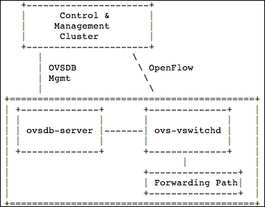
The ovsdb-server contains the OVSDB schema that holds all switching information for the virtual switch. The ovs-vswitchd daemon talks OpenFlow to any Control & Management Cluster, which could be any SDN controller that can communicate using the OpenFlow protocol.
Controllers use OpenFlow to install flow state on the virtual switch, and OpenFlow dictates what actions to take when packets are received by the virtual switch.
When Open vSwitch receives a packet it has never seen before and has no matching flow entries, it sends this packet to the controller. The controller then makes a decision on how to handle this packet based on the flow rules to either block or forward. The ability to configure Quality of Service (QoS) and other statistics is possible on Open vSwitch.
Open vSwitch is used to configure security rules and provision ACL rules at the switch level on a hypervisor.
A Leaf-Spine architecture allows overlay networks to be easily built, meaning that cloud and tenant environments are easily connected to the layer 3 routing fabric. Hardware Vxlan Tunnel Endpoints (VTEPs) IPs are associated with each Leaf switch or a pair of Leaf switches in MLAG mode and are connected to each physical compute host via Virtual Extensible LAN (VXLAN) to each Open vSwitch that is installed on a hypervisor.
This allows an SDN controller, which is provided by vendors, such as Cisco, Nokia, and Juniper to build an overlay network that creates VXLAN tunnels to the physical hypervisors using Open vSwitch. New VXLAN tunnels are created automatically if a new compute is scaled out, then SDN controllers can create new VXLAN tunnels on the Leaf switch as they are peered with the Leaf switch's hardware VXLAN Tunnel End Point (VTEP).
Modern switch vendors, such as Arista, Cisco, Cumulus, and many others, use OVSDB, and this allows SDN controllers to integrate at the Control & Management Cluster level. As long as an SDN controller uses OVSDB and OpenFlow protocol, they can seamlessly integrate with the switches and are not tied into specific vendors. This gives end users a greater depth of choice when choosing switch vendors and SDN controllers, which can be matched up as they communicate using the same open standard protocol.