Book Image

Mastering Ceph

By : Nick Fisk
Book Image

Mastering Ceph

By: Nick Fisk

Overview of this book

Mastering Ceph covers all that you need to know to use Ceph effectively. Starting with design goals and planning steps that should be undertaken to ensure successful deployments, you will be guided through to setting up and deploying the Ceph cluster, with the help of orchestration tools. Key areas of Ceph including Bluestore, Erasure coding and cache tiering will be covered with help of examples. Development of applications which use Librados and Distributed computations with shared object classes are also covered. A section on tuning will take you through the process of optimisizing both Ceph and its supporting infrastructure. Finally, you will learn to troubleshoot issues and handle various scenarios where Ceph is likely not to recover on its own. By the end of the book, you will be able to successfully deploy and operate a resilient high performance Ceph cluster.
Table of Contents (12 chapters)

Network design

A good network design is an important step to bringing a Ceph cluster online. If your networking is handled by another team, make sure that they are included at all stages of the design as often an existing network will not be designed to handle Ceph's requirements, leading to both poor Ceph performance as well as impacting existing systems.

It's recommended that each Ceph node be connected via redundant links to two separate switches so that in the event of a switch failure, the Ceph node is still accessible. Stacking switches should be avoided if possible, as they can introduce single points of failure and in some cases are both required to be offline to carry out firmware upgrades.

If your Ceph cluster will be contained purely in one set of switches, feel free to skip this next section.

Traditional networks were mainly designed around a North-South access path, where clients at the North, access data through the network to servers at the South. If a server connected to an access switch needed to talk to another server connected to another access switch, the traffic would be routed through the core switch. Due to this access pattern, the access and aggregation layers that feed into the core layer were not designed to handle a lot of intraserver traffic, which is fine for the environment they were designed to support. Server-to-server traffic is named East-West traffic and is becoming more prevalent in the modern data center as applications become less isolated and require data from several other servers.

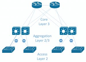
Ceph generates a lot of East-West traffic, not only from internal cluster replication traffic, but also from other servers consuming Ceph storage. In large environments, the traditional core, aggregation, and access layer design may struggle to cope as large amounts of traffic will be expected to be routed through the core switch. Faster switches can be obtained, and faster or more uplinks can be added; however, the underlying problem is that you are trying to run a scale-out storage system on a scale-up network design. Following image shows a typical network design with Core, Aggregation and Access layers. Typically only a single link from the access to the aggregation layer will be active.

A design that is becoming very popular in data centers is leaf-spine design. This approach completely gets rid of the traditional model and instead replaces it with two layers of switches: the spine layer and the leaf layer. The core concept is that each leaf switch connects to every spine switch so that any leaf switch is only one hop anyway from any other leaf switch. This provides consistent hop latency and bandwidth. Following is an example of a leaf spine toplogy. Depending on failure domains you may wish to have single or multiple leaf switches per rack for redundancy.

The leaf layer is where the servers connect into and is typically made up of a large number of 10G ports and a handful of 40G or faster uplink ports to connect into the spine layer.

The spine layer won't normally connect directly into servers, unless there are certain special requirements and will just serve as an aggregation point for all the leaf switches. The spine layer will often have higher port speeds to reduce any possible contention of the traffic coming out of the leaf switches.

Leaf spine networks are typically moving away from pure layer 2 topology, where layer 2 domain is terminated on the leaf switches and layer 3 routing is done between the leaf and spine layer. This is advised to be done using dynamic routing protocols, such as Border Gateway Protocol (BGP) or Open Shortest Path First (OSPF), to establish the routes across the fabric. This brings numerous advantages over large layer 2 networks. Spanning tree, which is typically used in layer 2 networks to stop switching loops, works by blocking an uplink, when using 40G uplinks; this is a lot of bandwidth to lose. When using dynamic routing protocols with a layer 3 design, Equal-cost multi-path (ECMP) routing can be used to fairly distribute data over all uplinks to maximize the available bandwidth. In the example of a leaf switch connected to two spine switches via a 40G uplink, there would be 80G of bandwidth available to any other leaf switch in the topology, no matter where it resides.

Some network designs take this even further and push the layer 3 boundary down to the servers by actually running these routing protocols on servers as well so that ECMP can be used to simplify the use of both NICs on the server in an active/active fashion. This is named Routing on the Host.

OSD node sizes

A common approach when designing nodes for use with Ceph is to pick a large capacity server, which contains large numbers of disks slots. In certain designs, this may be a good choice, but for most scenarios with Ceph, smaller nodes are more preferable. To decide on the number of disks each node in your Ceph cluster should contain, there are a number of things you should consider, some of the main considerations are listed as follows.

Failure domains

If your cluster will have less than 10 nodes, this is probably the most important point.

With legacy scale-up storage, the hardware is expected to be 100% reliable. All components are redundant, and the failure of a complete component such as a system board or disk JBOD would likely cause an outage. Therefore, there is no real knowledge of how such a failure might impact the operation of the system, just the hope that it doesn't happen! With Ceph, there is an underlying assumption that complete failure of a section of your infrastructure, be that a disk, node, or even rack should be considered as normal and should not make your cluster unavailable.

Let's take two Ceph clusters both comprising 240 disks. Cluster A comprises 20x12 disk nodes; Cluster B comprises 4x60 disk nodes. Now, let's take a scenario where for whatever reason a Ceph OSD node goes offline. It could be due to planned maintenance or unexpected failure, but that node is now down and any data on it is unavailable. Ceph is designed to mask this situation and will even recover from it whilst maintaining full data access.

In the case of cluster A, we have now lost 5% of our disks and in the event of a permanent loss would have to reconstruct 72 TB of data. Cluster B has lost 25% of its disks and would have to reconstruct 360 TB. The latter would severely impact the performance of the cluster, and in the case of data reconstruction, this period of degraded performance could last for many days.

It's clear that on smaller sized clusters, these very large dense nodes are not a good idea. A 10 Ceph node cluster is probably the minimum size if you want to reduce the impact of node failure, and so in the case of 60 drive JBODs, you would need a cluster that at minimum is measured in petabytes.

Price

One often cited reason for wanting to go with large dense nodes is to try and drive down the cost of the hardware purchase. This is often a false economy as dense nodes tend to require premium parts that often end up costing more per GB than less dense nodes.

For example, a 12 disk node may only require a single quad processor to provide enough CPU resource for OSDs. A 60 bay enclosure may require dual 10 core processors or greater, which are a lot more expensive per GHz provided. You may also need larger Dual In-line Memory Modules (DIMMs), which demand a premium and perhaps even increased numbers of 10G or even 40G NICs.

The bulk of the cost of the hardware will be made up of the CPUs, memory, networking, and disks. As we have seen, all of these hardware resource requirements scale linearly with the number and size of disks. The only area that larger nodes may have an advantage in is requiring fewer motherboards and power supplies, which is not a large part of the overall cost.

Power supplies

Servers can be configured with either single or dual redundant power supplies. Traditional workloads normally demand dual power supplies to protect against downtime in the case of a power supply or feed failure. If your Ceph cluster is large enough, then you may be able to look into the possibility of running single PSUs in your OSD nodes and allow Ceph to provide the availability in case of a power failure. Consideration should be given to the benefits of running a single power supply versus the worst case situation where an entire feed goes offline at DC.