
Understanding the zone-based firewall
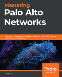
Traditionally, when considering the firewall as an element of your network, most likely you will imagine a network design like the one in the following image, with two to four areas surrounding a box. Most of the time, whatever is placed in the north is considered dangerous, east and west are somewhat grey areas, and the south is the happy place where users do their daily tasks. The box in the middle is the firewall.
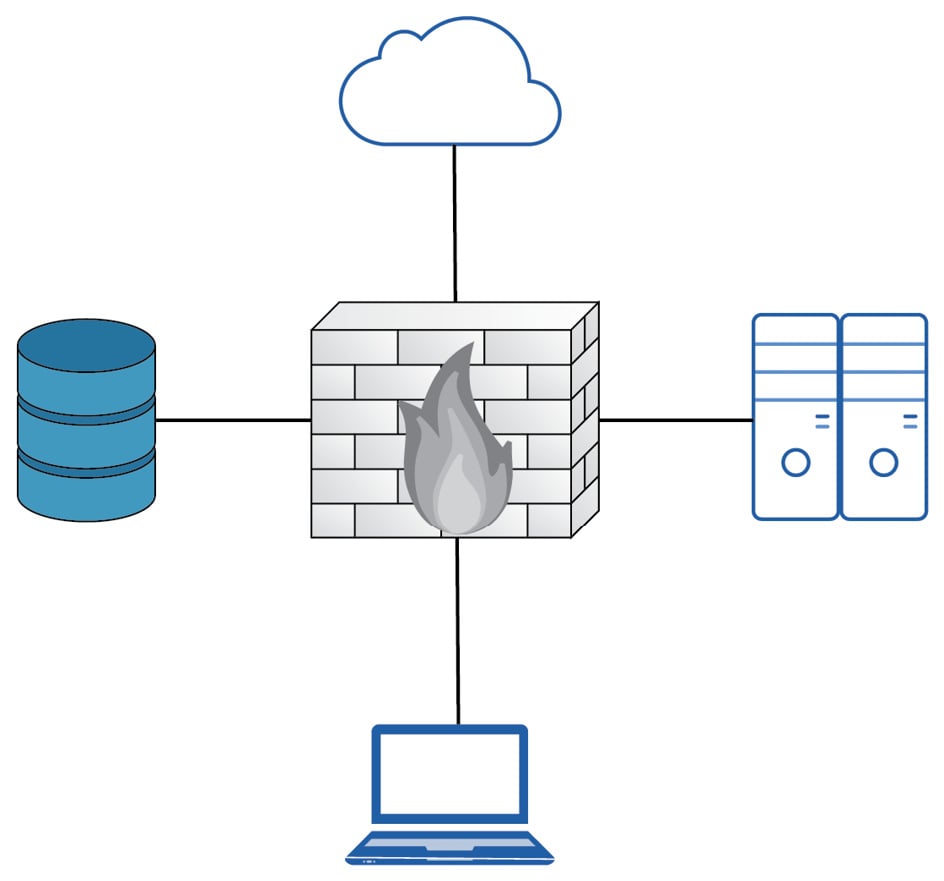
Figure 1.1 – Basic network topology
In reality, a network design may look a lot more complex due to network segregation, segmentation, remote offices being connected to the headquarters via all sorts of different technologies, and the adoption of cloud vendors.
In a route-based firewall, zones are simply an architectural or topological concept that helps identify which areas comprise the global network that is used by the company and are usually represented by tags that can be attached to a subnet object. They hold no bearing in any of the security decisions made by the system when processing security policies.
The zone-based firewall, on the other hand, will use zones as a means to internally classify the source and destination in its state table. When a packet is first received, a source zone lookup is performed. If the source zone has a protection profile associated with it, the packet is evaluated against the profile configuration. If the first packet is a TCP packet, it will also be evaluated against TCP state where the first packet needs to be a SYN packet, and a SYN-cookie is triggered if the protection profile threshold is reached. Then, a destination zone is determined by checking the Policy-Based Forwarding (PBF) rules and if no results are found, the routing table is consulted. Lastly, the NAT policy is evaluated as the destination IP may be changed by a NAT rule action, thereby changing the destination interface and zone in the routing table. This would require a secondary forwarding lookup to determine the post-NAT egress interface and zone:
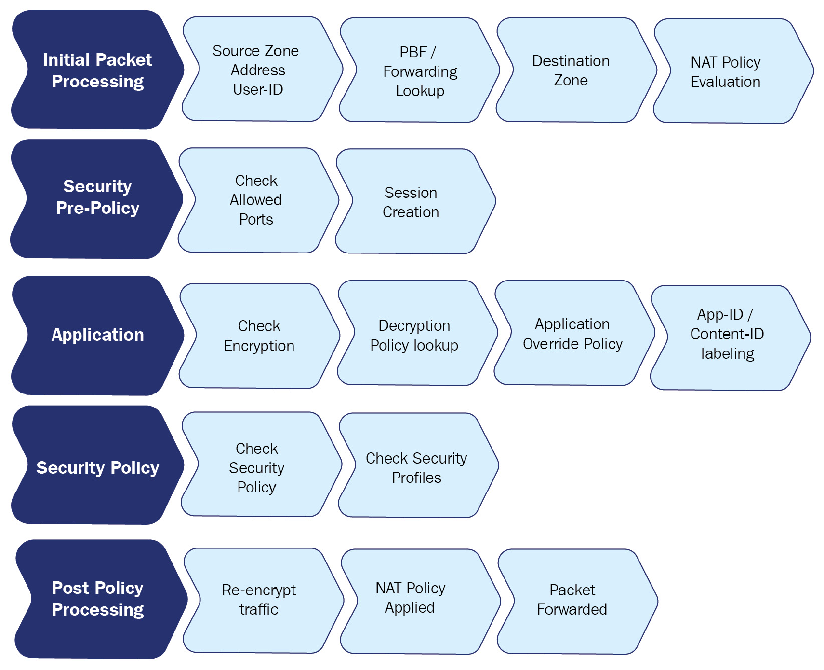
Figure 1.2 – Phases of packet processing
After these zone lookups have been performed, the firewall will continue to the security policy evaluation.
The policy evaluation then uses the 'six tuple' (6-Tuple) to match establishing sessions to security rules:
- Source IP
- Source Port
- Destination IP
- Destination Port
- Source Zone
- Protocol
Zones are attached to a physical, virtual, or sub interface. Each interface can only be part of one single zone. Zones can be created to suit any naming convention and can be very descriptive in their purpose (untrust, dmz, lan, and so on), which ensures that from an administrative standpoint, each area is easily identifiable.
It is best practice to use zones in all security rules and leveraging a clear naming convention prevents misconfiguration and makes security rules very readable. Networks that are physically separated for whatever reason but are supposed to be connected topologically (for example, users spread over two buildings that come into the firewall on two separate interfaces) can be combined into the same zone, which simplifies policies.
It is important to note that there are implied rules that influence intra- or interzone sessions. These rules can be found at the bottom of the security policy:
- Default intrazone connections: Packets flowing from and to the same zone will be implicitly allowed.
- Default interzone connections: Packets flowing from one zone to a different zone are implicitly blocked.
Security rules can also be set to only accept traffic within the same zone, between different zones only, or both. This way, an administrator could set a specific rule for the intrazone setting and allow all applications without inadvertently allowing this full access to be open to a different network. Adding a second zone to that same rule would allow the same access inside the new zone, but there would not be any access granted between the zones; that would require a new interzone or universal rule:
Figure 1.3 – Different security rule types and default rules
Let's now look at the expected behavior when determining zones.
Expected behavior when determining zones
When a packet arrives on an interface, the PBF policy or routing table will be consulted to determine the destination zone based on the original IP address in the packet header.
Let's consider the following routing table:
> show routing route
flags: A:active, ?:loose, C:connect, H:host, S:static, ~:internal, R:rip, O:ospf, B:bgp,
       Oi:ospf intra-area, Oo:ospf inter-area, O1:ospf ext-type-1, O2:ospf ext-type-2, E:ecmp, M:multicast
VIRTUAL ROUTER: default (id 1)
  ==========
destination       nexthop       metric flags  interface
0.0.0.0/0         198.51.100.1  10     A S    ethernet1/1
198.51.100.0/24   198.51.100.2  0      A C    ethernet1/1
198.51.100.2/32   0.0.0.0       0      A H
192.168.0.0/24    192.168.0.1   0      A C    ethernet1/2
192.168.0.1/32    0.0.0.0       0      A H
172.16.0.0/24     172.16.0.1    0      A C    ethernet1/3
172.16.0.1/32     0.0.0.0       0      A H
total routes shown: 7
Let's assume ethernet1/1 is the external interface with IP address 198.51.100.2 set to zone external, ethernet1/2 is the DMZ interface with IP address 192.168.0.1 set to zone dmz, and ethernet1/3 is the LAN interface with IP 172.16.0.1 and set to zone lan. The default route is going out of interface ethernet1/1 to 198.51.100.1 as next-hop. There are a few scenarios that will influence how the zone is determined:
- Scenario 1: A packet is received from client PC
172.16.0.5with destination IP1.1.1.1.The firewall quickly determines the source zone is lan and a route lookup determines the destination IP is not a connected network, so the default route needs to be followed to the internet. The destination zone must be external because the egress interface is
ethernet1/1. - Scenario 2: A packet is received from client PC
172.16.0.5with destination IP1.1.1.1but a PBF rule exists that forces all traffic for1.1.1.1to the next-hop IP192.168.0.25. As PBF overrides the routing table, the destination zone will become dmz as the egress interface is nowethernet1/2. - Scenario 3: A packet is received from internet IP
203.0.113.1with destination IP198.51.100.2. This is a typical example of what NAT looks like to the firewall: It receives a packet with its external IP address as the destination. From the perspective of the NAT policy, the source zone will be external as the IP is not from a connected network and no static route exists, and the destination zone will also be external as the IP is connected to that interface. From a security aspect, however, once NAT is applied, the destination zone will change to whatever NAT action is applied.Important note
Remember that NAT policy evaluation happens after the initial zones have been determined, but before the security policy is evaluated.