
Understanding the functions of network devices
On almost every network, there are a range of different devices that can be found, each with a unique function and purpose. In this section, we will discuss the functions of various network components. At the end, you will understand the roles each network device plays to ensure we have end-to-end connectivity over a network.
In the following subsections, we will discuss the functions and features of a Hub, Switch, Router, Firewall, Intrusion Prevention System (IPS), Access Point (AP), Cisco-based network controllers such as Cisco DNA and Wireless LAN Controller (WLC), and endpoints and servers.
Hubs
In today's world, you won't really find too many Hubs on enterprise networks. Hubs are a very old type of network intermediary device, used to interconnect computers, servers, printers, and other end devices to create a network. However, Hubs are now obsolete and are no longer recommended to be used in any network.
Let's take a look at how Hubs operate on a small network. Firstly, Hubs are devices used strictly for repeating any incoming signals they may receive on any of their physical interfaces. To get a better understanding of how Hubs forward traffic on a network, take a look at the following diagram:
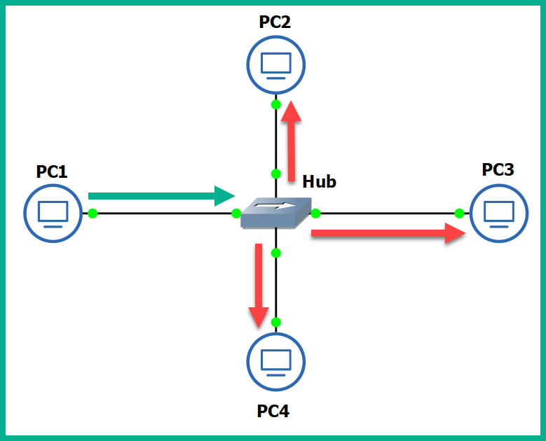
Figure 1.17 – Operations of a Hub
As shown in the preceding diagram, there are four computers connected to a unique physical interface (port) on the hub. In our scenario, PC1 wants to send a message to PC4. PC1 sends the message to the hub since it's the intermediary network device. The message is sent as an electrical signal along the network and to the hub. When the hub receives the signal, it rebroadcasts it out of all other ports, except the incoming port.
This means the message is also sent to unintended devices on the network, which is both a networking and security concern. First, let's understand the performance issues we can encounter if there are too many hubs as part of the network infrastructure. Any signal a hub receives is simply rebroadcasted out its other physical interfaces. Let's imagine there are multiple hubs being used on a single LAN for a building, where each hub is used to extend the physical network in order to interconnect all devices, such as network printers, desktop computers, and servers. Each time a device sends a message (signal) in a Hub's interface, it rebroadcasts it out of all the ports. This same signal will propagate to all the other interconnected hubs and do the same in the same manner, thus causing unnecessary broadcast (noise) traffic, which, in turn, will create network congestions. Think of it as a roadway being filled with too many vehicles, resulting in heavy traffic.
The following diagram shows the replication of the broadcast traffic through a small network:
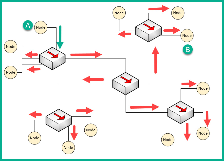
Figure 1.18 – Broadcast messages created by a Hub
Here, we can see that Node A sends a message to Node B but that the signal is being rebroadcast throughout the entire network.
What if you have two or more devices (nodes) transmitting messages at the same time over a Hub-based network? The result is the same as two vehicles colliding; in a network, this is known as packets colliding, which results in packets being corrupted. This means to ensure there is almost no collision, only one device should send their message at a time on the network. This creates a challenge because all the end devices on the network will be fighting to use the medium, thus creating a contention-based network.
To overcome such challenges, Carrier-Sense Multiple Access with Collision Detection (CSMA/CD) is used to help end devices such as computers to determine whether the media is clear (available) to transmit data (send a signal). Let's use a real-world analogy to explain how CSMA/CD works on a network. Imagine that, one day, you are shopping in the city and you want to visit various shops and stores. There are roadways separating them. Imagine the roadway is the media (wire) and you have to cross the road to reach the other store. Before crossing the road, you look both ways (left and right) a few times to ensure there are no vehicles (signals) passing and that it's safe to cross the street. Therefore, you are checking the media to ensure no vehicles (signals) are passing. When the media is clear, you proceed to walk across to the other side (transmit).
CSMA/CD ensures a device checks the media for a signal. If a signal is found on the media, the device waits and tries again at a later time. If the media is free, the device proceeds to transmit its message across the network.
However, network switches overcome this issue and devices do not have to check the media before transmitting their messages. In the next section, we will learn about the characteristics of switches.
Layer 2 switches
Switches are considered to be smart devices compared to hubs. Switches are devices that network professionals use to interconnect end devices (PCs, printers, servers, and so on) and extend the network infrastructure, typically extending a LAN within a building. As you may recall, in a hub, any incoming signal is rebroadcasted out all other ports. However, with a network switch, this is no longer the operational state. With a switch, when a device wants to send a message to another device, the switch directly forwards the message to the intended recipient.
The following diagram shows a small LAN where PC1 is transmitting a message to PC4 and the switch forwards the message only to PC4:
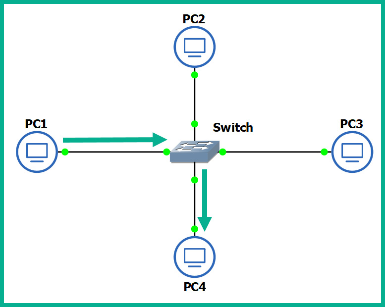
Figure 1.19 – Functions of a switch
You may be wondering, how is this possible? How does a switch defer from a hub? How does the switch determine which interface (port) the recipient is connected to? To put it simply, switches operate at the data link layer (Layer 2) of the OSI reference model. As you may recall, at the data link layer, the MAC addresses are inserted into the Layer 2 encapsulation header of the frame.
Switches are able to read the Layer 2 header information found in frames and create a table to temporarily store the MAC addresses it learned about on its interfaces. This table is known as the Content Addressable Memory (CAM) table in Cisco switches. Whenever a frame enters a switch's interface, the source MAC address of the frame is stored in the CAM table and is associated with the incoming interface.
To further understand how a switch populates the CAM table, let's imagine we have three PCs, all connected to a network switch to create a small LAN, as shown in the following diagram:
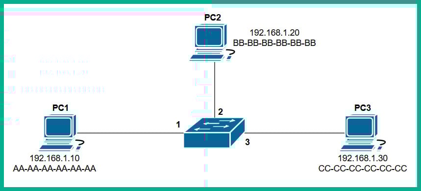
Figure 1.20 – Devices interconnected using a switch
Whenever a switch boots up, the CAM table is empty because its content is stored in Random Access Memory (RAM). Therefore, the content is lost whenever the device is powered off or rebooted. To begin, the CAM table is currently empty until end devices begin to exchange messages on the network.
Let's assume PC1 wants to send a message to PC3. Typically, we think both devices would use the IP addresses of each other to communicate on a local network, but this is not the case when it comes to working with network switches. Switches are only able to read the Layer 2 header of a frame, which contains source and destination MAC addresses, not IP addresses. There is no way for a network switch to read an IP header unless it's a Layer 3 switch; we will discuss Layer 3 switches in the next section.
PC1 knows the IP address of PC3 but not its MAC address. Therefore, PC1 sends an Address Resolution Protocol (ARP) request message on the network, requesting the IP address 192.168.1.30.
Important note
ARP is used to resolve IP addresses to MAC addresses on a network. Remember, for communication that happens on a local network, messages are exchanged via switches. This means each device uses MAC addresses to communicate with other devices on the same network.
The following diagram shows an ARP Request being sent through a network:
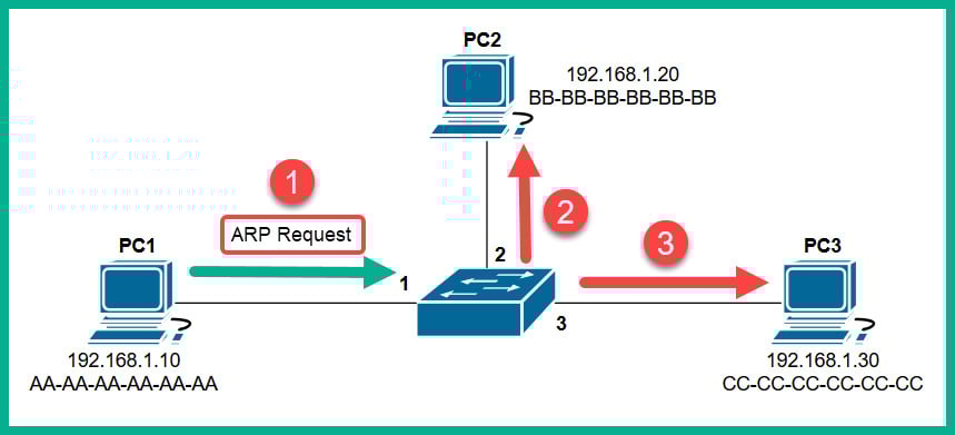
Figure 1.21 – ARP Request message
Each device on the LAN will receive the ARP Request message via a broadcast (all devices on the LAN receive the same message). At this point, the switch receives the ARP Request message on Interface 1 and populates the source MAC address on the CAM table, as shown here:
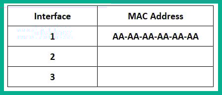
Figure 1.22 – CAM table
Only the device who has the IP address of 192.168.1.30 will respond with an ARP Reply, as shown here:
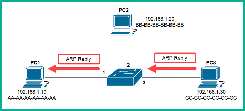
Figure 1.23 – ARP Reply
The ARP Reply message is a unicast transmission (device to device) and is sent directly to PC1. Keep in mind that the switch reads the frame header and populates the source MAC address into its CAM table, as shown here:
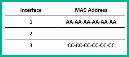
Figure 1.24 – CAM table
Additionally, the end devices also have their own ARP cache that temporarily records IP-to-MAC binding information. If there are no messages being exchanged between a MAC address for a predefined time interval, the operating system removes them from its ARP cache. On Cisco devices, the CAM table maintains a default inactivity timer of 300 seconds (5 minutes); this value can be modified.
Important note
To view the contents of the CAM table on a Cisco IOS switch, use the show mac address-table command.
To view the ARP cache on a Microsoft Windows operating system, follow these steps:
- Open the Command Prompt.
- Use the
arp –acommand and press Enter.The following snippet shows the ARP cache's contents on a Windows host computer on my network:
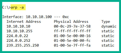
Figure 1.25 – ARP cache on a Windows machine
To view the ARP cache on a Linux operation system, use the following steps:
- Open the Terminal.
- Use the
arpcommand and press Enter.
The following snippet shows the ARP cache's contents on a Linux (Debian) host computer on my network:
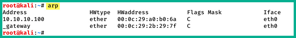
Figure 1.26 – ARP cache on a Linux machine
In both snippets, we can see that the ARP cache contains both IP-to-MAC address bindings of the other devices that exchanged messages.
Now that we have an understanding of how Layer 2 switches function, let's take a look at Layer 3 switches.
Layer 3 switches
Layer 3 switches have all the same functionalities as the Layer 2 switches. However, these devices come with an additional feature. They can read the information within an IP packet header, as well as the source and destination IP addresses. This enables the Layer 3 switch to interconnect two or more networks together and allows basic routing of IP packets between networks.
Keep in mind that Layer 3 switches do not have all the features of a Cisco router. In the next section, you will learn about the features and characteristics of a Cisco router.
Routers
A router is a device that is used to interconnect two or more different IP networks. These devices observe the destination IP address within the header of an IP packet, then check its local routing table for an available path to the destination's network when making its decision to forward the packet to the recipient.
Since routers can read and understand IP. They are considered to be Layer 3 devices due to their capabilities of reading IP information from packets. Without routers, end devices would not be able to communicate with devices residing on another IP network. The following diagram shows two IP networks, 192.168.1.0/24 and 172.16.1.0/16. Devices on the 192.168.1.0/24 network will only be able to intercommunicate between themselves; the same goes for the devices on the 172.16.1.0/24 network:
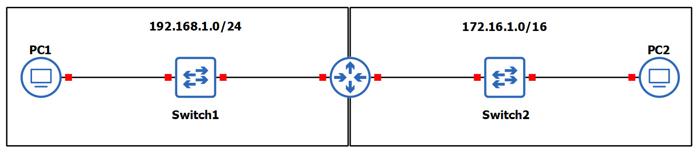
Figure 1.27 – Router interconnecting different networks
To allow both networks to exchange messages, a Layer 3 device such as a router is required. The router is used to interconnect these two different networks together. Additionally, the router acts at the default gateway for each of the networks. This means that if PC1 wants to send a message to PC2, the message must be sent to the doorway that leads to another network. This is the router in this scenario.
As a real-world example, your network at home is a private network and uses technologies a bit differently than those that are used on the ISP network and the internet. The following diagram shows a home network that is connected to the internet:
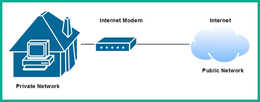
Figure 1.28 – Internet connection to a house
The private network uses a very different address space than what is used on the internet (public network). To allow communication between these networks, the ISP provides you with a modem, which has the capabilities of a router. This allows the ISP network to interconnect to your home (private) network. Lastly, the modem in this scenario acts as the default gateway for all your devices, providing a path to the internet.
Now that you have learned about the fundamentals of routers, let's cover the importance of implementing a firewall on an enterprise network.
Next-generation firewalls and IPS
A firewall is a network security appliance that is designed to filter malicious traffic, both inbound (entering a network) and outbound (leaving a network). Firewalls have an important role to play in networks of different sizes. These appliances typically sit at the network perimeter of an enterprise network, carefully inspecting all incoming and outgoing traffic, looking for any security threats and blocking them.
To get a better understanding of the benefits of using a firewall, let's use a simple analogy. A vehicle such as a car has a physical component called a firewall, which is the place between the cabin and the engine. The purpose of this component is important in the event of the engine of the car catching fire; the firewall will prevent most (if not all) the fire or heat from entering the cabin where the passengers are seated. Another analogy is a castle being surrounded by a moat and a single drawbridge that provides people with a single entry and exit point. In the event an opposing side wants to invade the castle, the drawbridge can be raised, and the moat will prevent the enemy from entering.
It is highly recommended to implement a firewall on your network. The internet contains millions of useful resources, from training videos to cooking recipes. However, there are many threats, such as malware and hackers, that roam the internet and attempt to infect and compromise systems. The firewall will act as the first line of defense against these threats.
The following diagram shows the typical deployment of a firewall on a network:
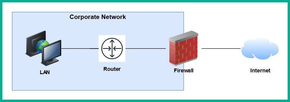
Figure 1.29 – Perimeter firewall deployment
Next-generation firewalls (NGFW) are designed to be superior in many ways, such as protecting the network and users from advanced threats, providing Deep Packet Inspection (DPI), preventing ransomware from entering the network, and having Virtual Private Network (VPN) features.
A firewall, by default, will allow traffic originating from the internal private network to go to all other networks, such as the internet. However, any traffic that is initiated from the internet to the internal corporate network is blocked by default. The firewall uses the concept of a security zone to help determine the level of trust it has for a logical network. When deploying a firewall, the security engineer must configure the interfaces of the firewall as a security zone with a trust level.
The following diagram shows the default security level for a Cisco Adaptive Security Appliance (ASA) firewall:
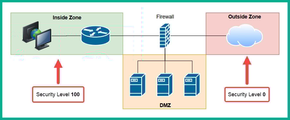
Figure 1.30 – Security zones of a firewall
The Inside Zone is usually your private, internal network, which is supposed to be a fully trusted and safe environment for all devices in the corporate network. This zone will normally hold a security level of 100 to indicate it's a fully trusted security zone. The firewall will allow all traffic originating from the Inside Zone with a security level of 100 to all other zones that have lower security levels. The internet as we know it is the most unsafe network in existence, being filled with extremely malicious malware and hackers, so the internet is usually assigned a security level of 0 as a Zero Trust zone. Any traffic that has been initialized from the internet to the Inside Zone will be blocked by default on the firewall. However, keep in mind that if a user on the Inside Zone has initialized a connection to the Outside Zone, the firewall will allow it by default, and if there is any returning traffic, the firewall will allow it as well. For example, as you open a web browser to visit www.google.com, the firewall will allow the HTTP GET message to the web server, and then the web server will send a response back the user's computer. In this case, the firewall will only allow the returning traffic.
Important note
Please note that the security-level schemes mentioned in this book are based on the Cisco technologies.
The Demilitarized Zone (DMZ) is a semi-trusted zone that's attached to the firewall on the corporate network. This zone is created to place servers that are accessible from the internet and the Inside Zone. The following are some guidelines for creating a DMZ on your network:
- The traffic initiating from the DMZ should not be allowed to access the Inside Zone.
- Rules should be created on the firewall to allow specific traffic to flow to the servers within the DMZ only. If there is a web server, then incoming HTTP and HTTPS traffic should be sent only to the web server.
- Ensure traffic initiating from the Inside Zone can access the DMZ.
Lastly, the security level of the DMZ should be between the value of the Inside and Outside Zones. However, within an organization, there many multiple trusted zones that have a security level closer to 100. There may be additional trusted zones, so the DMZ should have a security level of 50.
Intrusion Prevention Systems
An Intrusion Prevention System (IPS) is a component that is used to detect and block malicious traffic. In a traditional deployment, the IPS appliance usually sits in line of all incoming traffic and behind the firewall on the network. This type of deployment ensures the IPS can inspect all traffic as it passes through the appliance.
The following diagram shows the traditional IPS deployment model on a network:
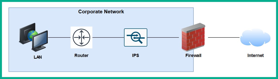
Figure 1.31 – Traditional IPS deployment
Traditional IPS appliances are deployed behind the firewall within the corporate network. Their purpose is to inspect any traffic and catch both suspicious and malicious traffic the firewall may have missed. Years ago, the IPS appliance was a separate physical device. However, with the advancement of technologies and innovation, Cisco has integrated the IPS into their next-generation firewall appliances as a module. The benefits of this are a less physical appliance and a firewall interface that provides a single management dashboard for both the Cisco IPS and firewall all-in-one appliance. This allows a firewall administrator to enable the IPS feature with the use of a license key provided by Cisco systems.
Next-generation IPS (NGIPS) inspects and filters traffic a bit differently to a firewall. The IPS downloads a database of malware signatures from TALOS, Cisco's Security Intelligence and Research Group. It uses this information to closely inspect all traffic flowing through it to identify any malicious traffic. Additionally, the IPS can be manually configured with predefined rules created by a security engineer. It can also automatically learn the behavior of the network to catch abnormal traffic types. The awesome benefit of having an IPS on a network is that if it detects any malicious traffic, it can stop it in real-time, preventing the attack.
Tip
If you're interested in building your own IPS device, check out Snort at www.snort.org. Snort is an open source intrusion prevention system application.
On the other hand, IDSes are considered to be reactive devices compared to IPSes. An IDS is configured to receive a copy of the network traffic, detect security threats, and send alerts. IDSes are not implemented in-line with network traffic, so they do not have the capability to stop an attack as it happens on a network. Furthermore, the IDS only sends an alert after an attack has happened, which makes it reactive in nature.
Now that we have learned about the functions of firewalls and IPSes, let's take a look at a device that allows us to extend a wired network into a wireless one.
Access Points
An Access Point (AP) is a device that allows you to extend a wired network into a wireless frequency, allowing wireless-compatible devices to connect and access the resources on the wired network.
This provides many benefits, such as the following:
- Increases the mobility of users and roaming within a compound
- Reduces the need for physical cabling
- Increases ease access to a network
Wireless APs use a wireless radio frequency, which is broadcast from the AP using the 2.4 GHz and/or 5 GHz channels. This allows mobile devices with a compatible wireless NIC to listen on these frequencies and connect to an AP. Most commonly, the 2.4 GHz APs are found almost on every wireless network due to the fact it was the first type of AP produced and a lot of organizations and home users invested in the technology.
Important note
The 2.4 GHz channel provides a lower frequency and gives a greater distance.
As there are so many building and homes equipped with a 2.4 GHz AP, the radio airways of 2.4 GHz are now a very saturated space, where each device is trying to transmit their data to clients without causing interference. This has become almost impossible now. The 2.4 GHz band uses a total of 11 channels; however, it is recommended to use channels 1, 6, and 11 to ensure there is no overlapping.
The following diagram shows the recommended clean channels of the 2.4 GHz channels:
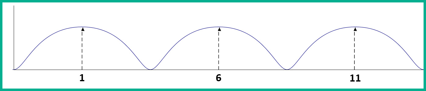
Figure 1.32 – Wireless channels range
However, even this recommendation is no longer beneficial. An AP can be using channel 2, 4, or even 8, which will create an overlap (interference) between the recommend channels (1, 6, and 11).
The 5 GHz frequency provides a lot more channels, thus creating less interference among nearby Access Points that are operating on the 5 GHz frequency. The downside of using 5 GHz is the short distance the signal can travel. However, this may be a benefit. Let's imagine that a company with multiple floors in their building are deploying the 5 GHz frequency Access Points; because the 5 GHz frequency travels much shorter distances, this means the possibility for one AP's signal to interfere (overlap) with another AP who is using the same frequency has been reduced.
Important note
In later chapters of this book, we will discuss wireless architectures in more depth.
Having covered the purpose of using Access Points, let's take our discussion a bit further and describe how to improve the management of our corporate wireless network.
Cisco Wireless LAN Controller (WLC)
Wireless LAN (WLAN) is simply defined as a wireless network containing either a single Access Point at home for personal use or an organization containing multiple Access Points to provide wireless connectivity between employees' mobile devices (smartphones, tablets, and laptops) and the wired network infrastructure. With the increase of wireless networking, a lot of companies are implementing a Bring-Your-Own-Device (BYOD) policy to ensure an acceptable level of security is established and maintained. However, for network engineers, this means the wireless network needs to be able to support the large number of portable devices that are connecting and exchanging messages on the WLAN.
This will result in network professionals having to implement a robust wireless network with multiple APs throughout the organization, on each floor and room where a wireless signal is needed or required. Let's imagine that our fictional company, ACME Corp, own a 10-storey building and that the network administrators have to implement Access Points. One key aspect is to maintain the consistency of each AP's firmware, configurations, and security settings. Imagine that, after the deployment of the wireless network, the network administrator has to make a change on the WLAN that will affect all Access Points. It's definitely not efficient to log into each Access Point and manually make the changes in the device's configuration as this is time-consuming and prone to human error.
A WLC allows a single management interface for the entire wireless network. This device enables you to control any number of APs on a network. Therefore, you can simply log into a WLC and configure the entire WLAN, providing a centralized management platform for network professionals. In later chapters, we will cover various deployment models for Access Points and wireless LAN controllers in more detail.
Endpoints and servers
So far, we have been talking about intermediary devices that connect us to a network and the internet. However, we must not forget about the simple yet cool devices that allow us to communicate on a network and provide resources to others: endpoints and servers.
Servers are devices that run specialized applications that enable them to provide resources to users on a network. To get a better idea of the functionality of a server, let's imagine you work for a small business with approximately 30 employees, all residing in a single building. Each employee has their own company-issued laptop or desktop computer fitted with all the relevant software applications for each person to complete their duties efficiently. Each day, employees may be creating new documents and files that have to be shared with others in the organization; however, emailing each file to a user or group may not always be the best way to efficiently collaborate on a project.
In this case, a centralized file server can be set up within the company's network to allow various persons or all employees to centrally store their work-related files on the file server, rather than storing them locally on their computers (endpoints). In this scenario, the server is hosting files for the organization or the client (endpoint) devices to access.
Keep in mind that client devices (endpoints) are usually devices that are connected to a network to access a resource. These might be laptops, smartphones, tablet computers, desktop computers, and so on.
Cisco DNA
The Cisco Digital Network Architecture (DNA) is an IP-based software solution designed by Cisco Systems to provide engineers with applications they can use to manage, automate, and gather intelligence analytics, as well as monitor security, on a Cisco network across multiple devices and platforms.