In the networking world, TCP and IP are the most popular and frequently used protocols to transport and deliver data to and from the application layer, hence the name of the protocol suite, TCP/IP. However, some application-layer protocols use UDP over TCP for many reasons. In this section, you will explore the characteristics of all three protocols and how they work together to ensure devices are able to exchange messages.
Transmission Control Protocol
The application-layer protocols of the TCP/IP protocol suite do not have any capabilities to ensure their datagram (data) is successfully delivered to their destination. The application-layer protocols are designed to interpret the messages or data that are being sent and received by a device. Unfortunately, there are no mechanisms that are built into them. This is where the transport-layer protocols come in to save the day.
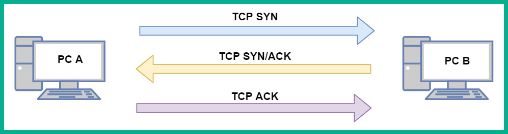
One such Layer 4 protocol to help with the delivery of datagrams is TCP. TCP is known as a connection-oriented protocol, which ensures messages are delivered to their destination. For TCP to provide such reassurance and guarantee of delivery, a TCP three-way handshake is established between a source and destination before exchanging messages (data). For a TCP three-way handshake to be established, two devices must exchange a series of TCP synchronization and TCP acknowledgement messages before they can exchange data.
The following diagram shows two devices establishing a TCP three-way handshake:
Figure 1.11 – TCP three-way handshake
After the TCP three-way handshake has been established between the two devices, they will begin to send data between each other. During a TCP connection, for every message a device sends to a destination, an acknowledgment is expected to be returned indicating the message was successfully delivered. If the sender does not receive an acknowledgment from the destination after a period of time, the sender will retransmit the data until the destination returns an acknowledgment. This is how TCP provides the guaranteed delivery of messages between a source and destination on a network.
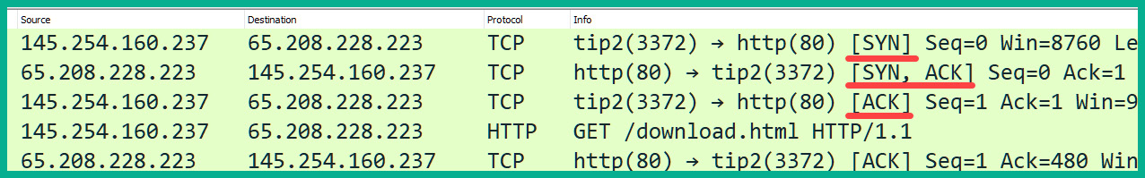
To get a better understanding of how devices see the TCP three-way handshake, let's take a look at the following HTTP traffic capture on Wireshark:
Figure 1.12 – Observing a TCP three-way handshake in Wireshark
The following are the details of the transactions that occur in the first three packets in the preceding capture:
- As you can see, the sender (Device-A) with the IP address
145.254.160.237 is sending a TCP SYN packet over to Device-B at 65.208.228.223. The TCP SYN message simply informs the destination device that the sender wants to initiate a TCP three-way handshake and exchange some messages. The following snippet shows the details of packet #1:
Figure 1.13 – Observing the SYN flag
- When Device-B receives the TCP SYN message, it will then respond with a TCP SYN/ACK message back to the sender, Device-A, indicating it would like to establish a session and acknowledges the SYN message. In a single packet, both the SYN and ACK flags will be set. We can see this in the following screenshot:
Figure 1.14 – Observing SYN and ACK flags in a packet
- Lastly, when Device-A receives the TCP SYN/ACK message, it will then respond with a TCP ACK message. This is the final stage in establishing the TCP three-way handshake. From this point forward, for all other messages that are exchanged between Device-A and Device-B, a TCP ACK message is returned to the sender to confirm that the message has been successfully delivered.
Using TCP seems to be the preferred transport-layer protocol, right? To put it simply, TCP has some drawbacks in certain situations and various application-layer protocols. The following are some well-known disadvantages of using TCP:
- TCP has more overhead on a network. For each bit of data sent, an acknowledgment message must be returned. Imagine streaming a video on YouTube. For each message the media server sends to you, your computer has to send an acknowledgment packet back to the server. This additional network traffic will eventually flood and congest the network as more users stream media from YouTube.
- TCP does not work well for time-sensitive traffic types. Traffic types such as Voice over IP (VoIP) and Video over IP rely heavily on the speed of a network to ensure both the sender and receiver are experiencing the conversation in real time. Imagine, during a VoIP call, the sender has to wait for the acknowledgment packets for each message it has sent to the destination before the sender is able to forward more messages to the destination.
Now that you have a clear idea about the functionality and role TCP plays in a network, let's take a look at the features of UDP in the next section.
User Datagram Protocol
UDP is described as a connectionless transport-layer protocol. Connectionless means UDP does not establish any logical sessions between a sender and receiver; it simply sends the messages to the destination without any prior checks like TCP. Imagine you are sending physical mail via your local courier service to a friend. You deposited the letter containing all the proper addressing information at the local postbox. From that point onward, you don't have any tracking information or confirmation of delivery for the letter. What if the person has moved to another location? How will you be notified? Similarly, this is how UDP works. It sends messages without establishing a session and it does not provide a guarantee of delivery.
If you recall in the previous section, TCP will resend a message if the sender does not receive an acknowledgment from the destination. UDP will send messages as quickly as the protocol is receiving PDUs from the application layer, even if the messages are sent out of order. UDP uses best-effort when sending messages across a network.
Both the TCP and UDP protocols are vital to ensure the next protocol, IP, is able to carry the actual data to its intended destination. In the next section, you will learn about the fundamentals of IP.
Internet Protocol
Without the IP, a device will not be able to communicate across networks. The
transport-layer protocols, such as TCP and UDP, support the IP with its delivery of messages between a sender and receiver. IP is the driving force behind all computer-based networks and is used to carry messages between devices.
IP has the following characteristics and functionality on a TCP/IP network:
- IP is connectionless and does not establish a session between the sender and receiver devices prior to forwarding any messages.
- IP also forwards network traffic using best-effort and does not provide any sort of reassurance to the sender that its messages will be successfully delivered to the destination or even in sequential order.
- IP is designed to operate independently from the network media. To put it simply, the contents of an IP packet are not affected by the type of network cabling or radio frequencies that are used at the physical layer of a network.
Now that you have learned about the characteristics of the IP, let's take a deeper dive to learn more about IPv4 addressing schemes and their structure in the next section.
IPv4
In the early 1980s, IPv4 address spaces were made available to organizations, which enabled them to assign a unique IPv4 address to each device on their network and the internet for communication and the sharing of resources. The Internet Assigned Numbers Authority (IANA) created and manages the IP address spaces for the entire world.
In the computing world, devices are able to understand ones (1s) and zeros (0s), which are commonly referred to as bits. These are physically represented in the form of an electrical signal being high (1) or low (0) on a system. Each device on a network requires a logical address to communicate with one another – this address is an IP address. An IPv4 address has a total length of 32 bits. This address is written in the following decimal format, which most of us are familiar with: 192.168.1.10.
The preceding address is written in decimal format. However, notice how each number is separated by a period (.). Each of those numbers within the IPv4 address is known as an octet. An octet is made up of 8 bits in the range 00000000 – 11111111. This means an octet ranges from 0 to 255 in decimal notation.
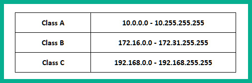
In the IPv4 world, the IANA has designed some addresses that can be allocated for private use, while another group of addresses was allocated for usage on the internet. The private IPv4 addresses are non-routable on the internet. This means any device that has a private IPv4 address assigned to it will not be able to communicate with any device on the public address space, which is the internet.
The following table shows the classes of private IPv4 address spaces:
Figure 1.15 – Private IPv4 address spaces
Each class of private IPv4 address can be assigned to devices on a private network. Additionally, this address space does not have to be unique between organizations simply because they are non-routable on the internet. Company A can implement any of the private IPv4 classes within their network and so can other organizations without creating any issues or conflict.
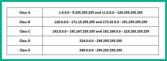
The following are the classes of public IPv4 address spaces:
Figure 1.16 – Public IPv4 address spaces
The addresses shown in the preceding table are those that can be used on the internet and are routable on public networks. Each device that is directly connected to the internet, such as your firewall or edge router, must be assigned a unique public IPv4 address. The assignment of a public IPv4 address to an organization's edge devices is usually done by their Internet Service Provider (ISP). Keep in mind, the missing IPv4 address spaces shown in Figure 1.16 belong to the IPv4 private address space.
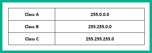
For each class of IPv4 address, there's an associated subnet mask address. The subnet mask has a very important role; it's also 32 bits in length, and helps the computer or device to determine which portion of the IPv4 address is the network portion and which is the host portion.
The following table shows the subnet mask for each class of IPv4 address:
Figure 1.17 – Subnet masks
An IP address is made up of two portions: the network and the host portion. The network portion of an IP address is like the community address of your neighborhood – everyone has the same community address as you but your house/apartment number is unique to your residents. The host portion of the IP address is unique to the host device on the network; therefore, overall, the entire IP address is unique on the network.
The subnet mask is used to help a device such as a router or even your computer to determine which portion of the IP address belongs to the network and which portion belongs to the host.
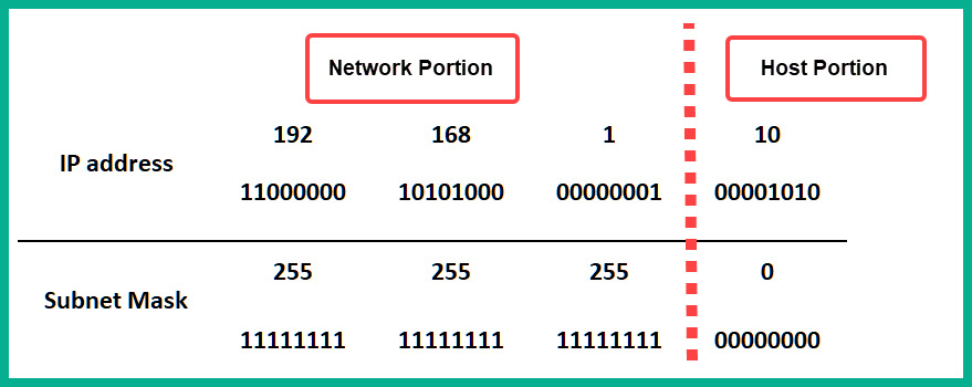
In the following snippet, you will notice that we have converted both an IP address and subnet mask into binary notation, such that each bit within the IP address and subnet mask is aligned. The 1s in the subnet mask are used to represent the network portion of the IP address, while the 0s are used to represent the host portion:
Figure 1.18 – Determining the network and host portions of an IP address
As shown in the preceding figure, we use a Class C IPv4 address, 192.168.1.10, with its default subnet mask of 255.255.255.0, which allows us to determine the network and host portions of the IPv4 address.
A subnet mask can be written in a shortened version known as a network prefix. The network prefix is a simplified representation of the number of ones in a subnet mask. Therefore, a subnet such as 255.255.255.0 contains a total of 24 ones, so we can represent this subnet mask by simply writing it as /24. Another example: let's imagine a computer has an IPv4 address of 172.16.2.2 with a subnet mask of 255.255.0.0. This entire address can be represented in the format 172.16.2.2/16.
Tip
If you are interested in learning more about IPv4 subnetting and techniques, be sure to check out this tutorial: https://hub.packtpub.com/understanding-address-spaces-and-subnetting-in-ipv4-tutorial/.
Furthermore, the subnet mask is used to help end devices determine whether the destination for the messages exists on the same network as the sender or on a remote network. The subnet mask is also used to determine the network ID of the sender and compare it with the destination IP address. The network ID is simply the community that a device resides on. If the network IDs of the sender and the destination match, the sender will forward the message to the destination directly by inserting the destination's IP address and its MAC address in the message.
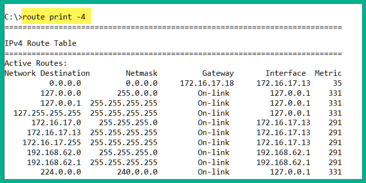
The following snippet shows the routing table on a Windows 10 computer:
Figure 1.19 – Checking the Windows 10 routing table
If the network IDs of the source and destination do not match, the sender will insert the destination's IP address in the Layer 3 header of the packet and the default gateway's MAC address as the destination MAC address of the Layer 2 header in the frame. Therefore, the sender will forward its message to the default gateway, which will inspect the destination IP address in the Layer 3 header and forward it to the intended destination.
To determine the network ID, the process of ANDing the IP address and subnet mask is required. The following are the laws of ANDing:
1 AND 1 = 1
1 AND 0 = 0
0 AND 1 = 0
0 AND 0 = 0
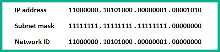
To apply this technique, let's use an example such as determining the network ID of a computer with an IP address of 192.168.1.10 and a subnet mask of 255.255.255.0:
Figure 1.20 – Determining a network ID
The network ID is 192.168.1.0/24. This process happens each time the source wants to send a message to another device. It has to determine whether the destination host is on the same network as the source or on another IP subnet.
IPv6
The IPv4 public address space was destined to eventually be exhausted as more devices came online. This happened a bit sooner than expected. In 2013, it was announced that IPv6 had started making its way onto the internet to support newly connected devices with the new address scheme. On the positive side of things, IPv6 was designed to be lightweight compared to the structure of an IPv4 packet.
An IPv6 address is 128 bits in length and is written using hexadecimal characters that range from 0 to 9 and A to F. The following is an example of an IPv6 address:
2001:0DB8:0000:1111:0000:0000:0000:0200
A colon (:) is used to separate the hextets from one another. A hextet is made up of 16 bits, therefore 8 hextets x 16 bits per hextet = 128 bits in total. Unlike IPv4, IPv6 has a lot more available addresses with an approximate value of 10^36 IPv6 addresses in the world. With this large number, there is no need for public or private address spaces in the IPv6 world. Devices are assigned a global unicast IPv6 address that is routable on the internet as a public IPv4 address.
Important note
The default subnet mask for an IPv6 address is /64. Additionally, /64 bit is the global prefix on IPv6 that corresponds to the network address of IPv4.
Keep in mind that IPv6 and IPv4 exist in two different logical spaces and therefore, they are unable to talk to each other natively. However, various networking technologies and IP services, such as NAT64, tunneling (6to4 and 4to6), and dual stacking, make it possible for devices to communicate on both an IPv4 and IPv6 network.
The Internet Control Message Protocol
Another important network-layer protocol is the Internet Control Message Protocol (ICMP). ICMP is designed to provide error reporting details to networking professionals such that a network administrator or engineer can use various tools, such as ping and traceroute, which utilize ICMP to validate the causes of network connectivity issues. A cybersecurity professional also uses various security tools, such as Nmap, to assist in profiling and determining security configurations on target systems such as end devices and security appliances.
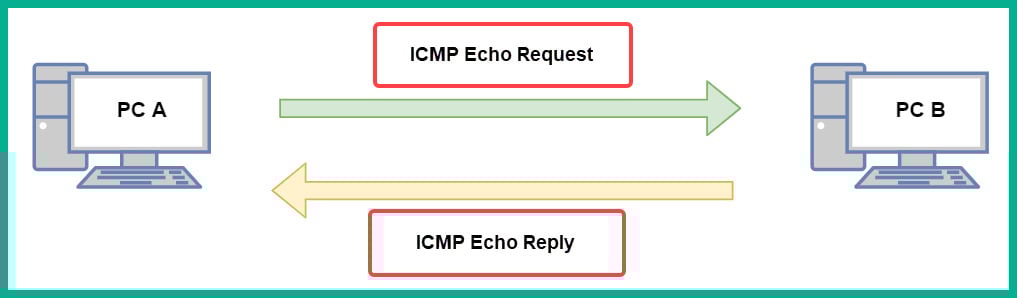
ICMP operates by sending an ICMP echo request message from the sender device over to the destination. Once the destination device receives the message, it will process it and respond with an ICMP echo reply back to the sender. This is an indication that there is network connectivity between the sender and destination devices.
The following diagram shows a visual representation of this concept:
Figure 1.21 – ICMP messages between two devices
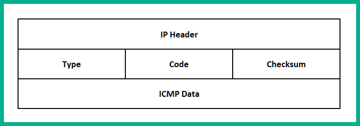
To get a better understanding of how ICMP works, let's take a look at an ICMP packet structure and break down the fields to understand their purpose. The following diagram shows a simplified representation of an IP packet and its respective fields:
Figure 1.22 – ICMP packet structure
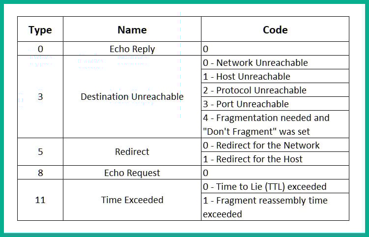
The following is a description of each field in the ICMP packet structure:
Figure 1.23 – ICMP types and codes
- Checksum: This is used to represent a one-way cryptographic hash value of the entire packet. The hash value is used by the destination device to check the integrity of the packet, such as whether it was modified or corrupted during transmission.
- ICMP Data: This field usually contains additional ICMP information about the packet.
Next, you will learn how to use Wireshark, a network protocol analyzer, to inspect ICMP messages.
Lab – inspecting ICMP messages with Wireshark
To get a better idea of how ICMP works, let's use the ping utility within the Windows operating system to test the connectivity between your local machine and Google's public DNS servers. Additionally, we will be using Wireshark to analyze network traffic.
To complete this exercise, use the following steps:
- To download Wireshark, go to https://www.wireshark.org/. Once the file has been downloaded onto your system, install it using all the default settings.
- Open Wireshark and double-click on your NIC to begin capturing traffic:
Figure1.24 – Selecting an NIC on Wireshark
- Once the capture has started, in the Display Filter bar, type
icmp and hit Enter. This will show only ICMP messages on Wireshark, as shown here:Figure 1.25 – ICMP filter on Wireshark
- In Windows, open Command Prompt. Enter the
ping 8.8.8.8 command and hit Enter, as shown here:Figure 1.26 – Testing connectivity using ping
- Your computer sent four ICMP echo request messages. Each of these messages contains ICMP Type 8 Code 0 details. To inspect this packet, select the first ICMP packet and take a look at the packet details, as shown here:
Figure 1.27 – Observing ICMP echo request messages
- Next, select the next ICMP packet. This should be an ICMP echo reply. This packet contains an ICMP Type 0 Code 0 in its details:
Figure 1.28 – Inspecting ICMP reply messages
- Lastly, click the red square icon at the top left of the Wireshark interface to stop the capture.
Having completed this lab, you have gained the essential skills to perform the inspection of various types of ICMP messages, their types, and the code within each packet.
Now that you have completed this section, you have gained the fundamental knowledge of being able to describe the functions of each network layer of both the OSI reference model and the TCP/IP protocol suite.


 Free Chapter