
Understanding the interface types
When you open the Network | Interfaces menu, you will see an assortment of physical interfaces.
There are several different interface types that will cause an interface to behave in a specific way. We will first cover the four basic interface types and continue with the more specialist ones after:
- Virtual Wire (VWire)
- Layer 3
- Layer 2
- Tap
Let’s discuss them in more detail.
VWire
Just as the name suggests, VWire is intended to be a “bump in the wire.” VWire always consists of two physical interfaces—no more and no less. There is no low-level interference with VLAN tags and there are no routing options; packets are inspected in flow.
Using a VWire interface can be an easy way to “drop in a firewall” without needing to interfere with an existing routing or switching environment. It easily plugs in in front of an ISP router or can be placed in between a honeypot and the network to add a layer of detection.
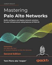
Before you can create a VWire interface, you first need to set two interfaces to the Virtual Wire type and assign each of them a different zone:
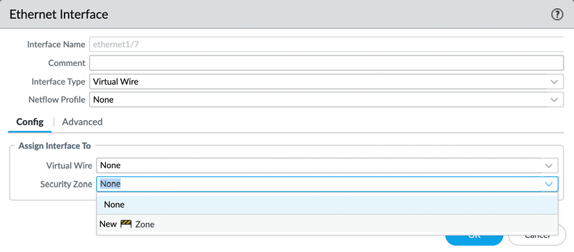
Figure 2.45: VWire interface
You can now connect both interfaces in a VWire profile by going to Network | Virtual Wires and creating a new VWire profile.
As illustrated in the following screenshot, you will need to select the two interfaces that you will form a VWire connection with. If the VWire interface is placed over a trunked link (one that contains the VLAN/802.1Q tags), you need to indicate which ones are allowed. If you want to allow all tags, set 0-4094. If you want to add single tags or ranges, you can add integers or ranges, separated by commas (for example, 5,15,30-70,100-110,4000). Multicast firewalling needs to be checked if you want to be able to block or otherwise apply security policies to multicast traffic. If unchecked, multicast is forwarded across VWire.
Link State Pass Through brings the opposite interface down if one side loses its connection. This ensures that both the client and server sides see the link go down and respond accordingly:

Figure 2.46: VWire configuration
Next, let’s look at the Layer 3 interface.
The Layer 3 interface
A Layer 3 interface is a routed interface. This means it has an IP address and can be used as a default gateway for clients on the inside connected to it or a next hop for a routing device. On the outside, it can communicate with ISP routers and forward traffic out to the internet.
In the Config tab of the interface, you need to assign a Virtual Router (VR) and a security zone. This zone will represent the subnet(s) connected to it when traffic needs to flow from one interface to another:
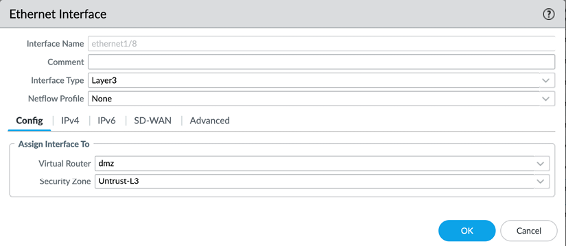
Figure 2.47: Layer 3 interface configuration
The IP configuration can be statically configured as an IP/subnet. If needed, multiple IP/subnets can be added to represent additional networks that are directly connected to the interface.
Remotely connected networks (located behind a router) can be configured in the VR field:
Figure 2.48: Layer 3 interface IP
A Layer 3 interface can also be set as a Point-to-Point Protocol over Ethernet (PPPoE) client if the upstream connection is provided by a broadband ISP over cable or DSL.
In the General tab, the ISP authentication username and password can be configured:

Figure 2.49: Layer 3 PPPoE
In the Advanced tab, you set the authentication protocol to PAP, CHAP, auto, or none. If the ISP has provided you with a static IP, you can configure it here and you can add an access concentrator and service string if the ISP requires them to be able to connect. If required, you can disable adding the default route received by the ISP to the routing table. Some ISPs require PPPoE clients to be in a passive state as they initiate the connection. You can enable this here:
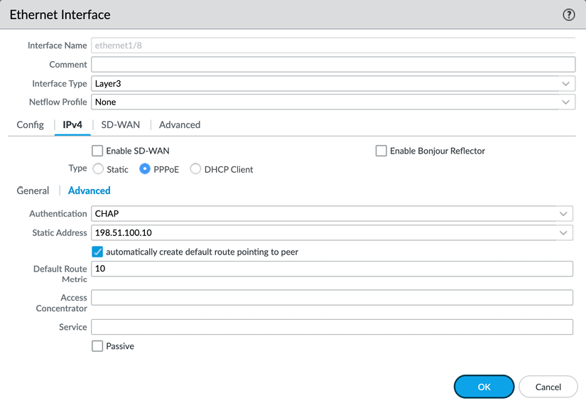
Figure 2.50: Layer 3 PPPoE advanced options
Once you’ve configured the interface and have committed the change, click on Show PPPoE Client Runtime Info to return information on the connection. From the CLI, you can issue the following command to see the same output:
admin@PA-220> show pppoe interface <interface>
For the Layer 3 subnets and IP addresses to be reachable across interfaces, they need to be added to a routing table; this is accomplished in the virtual router.
Virtual router
A VR is the routing element of the firewall, but, as the name suggests, it is not made up of a single engine, but rather a routing set that an interface is subscribed to. Each Layer 3, loopback, and VLAN interface needs to be associated with a VR, but multiple VRs can be used on a system. Not all interfaces need to be associated with the same VR. You can configure the default VR or add new VRs from the Network | Virtual Routers menu.
In the Router Settings tab of a VR, you can see and add interfaces associated with this VR, and adjust the administrative distances if needed. An administrative distance associates a priority with a routing protocol. By default, static routes have a higher priority (lower administrative distance) than OSPF (Open Shortest Path First), but you can change this priority if you want OSPF routes to have priority and only use static routes if OSPF becomes unavailable. Routes within the same routing protocol can be assigned a metric to give them a higher (lower metric) or lower (higher metric) priority. Routes with the same metric are prioritized based on the size of their subnet. A smaller subnet (for example, /32) will have priority over a larger subnet (for example, /16):

Figure 2.51: VR settings
In the Static Routes tab, you can add destination routes as needed. By default, the firewall loads all the connected (configured on a Layer 3, loopback, or VLAN interface) networks in the routing table; adding static routes makes remote networks available from a routing perspective.
One of the first routes you may need to configure is the “default route,” which allows clients to connect to the internet.
The destination for the default route is 0.0.0.0/0. A regular route could have a smaller subnet, such as 172.16.0.0/24.
The Interface option indicates what the egress interface will be. If the route is pointing to the internet, the interface will be the one where the ISP router is connected.
- IP Address: The IP of the upstream router to forward packets to.
- Next VR: Whether the packet needs to be handed over to a different VR on the same device.
- FQDN: If the upstream router has a dynamic IP, it could be useful to use an FQDN that is dynamically updated by a DNS record.
- Discard: Routes can be set to “black hole” certain subnets. This can be used to prevent any packets from reaching a connected out-of-band network, even if a security policy were to allow this.
- None: Routes may not have a next hop, such as packets routed into a VPN tunnel.
The Admin Distance and Metric settings can be changed for each route if necessary.
Route Table is used to add routes to regular unicast routing, multicast routing, or both.
You can, if you have redundancy available, use Path Monitoring to send a heartbeat ping over the route. If the ping fails a configured amount of times, the route will be disabled. The routing table will be re-evaluated for matching packets and the next best match will be used to route packets (that is, a route with a higher metric or larger subnet):
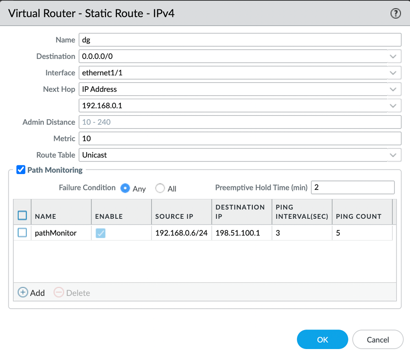
Figure 2.52: VR default route
Any subnets that are configured on a Layer 3 interface are added to the routing table as a connected network and do not need a static route to be added.
The Layer 2 interface and VLANs
Setting interfaces to the Layer 2 type enables the firewall to function in a similar way to placing a switch in the network. Each interface acts as the equivalent of an access port (if you need trunk functionality, refer to the Subinterfaces topic) on a switch, and you can add as many interfaces as you need.
Each interface should use a different zone so that a security policy can be leveraged to control traffic between the interfaces. Interfaces set to the same zone will, by default, exchange traffic without inspection and require a catch-all security policy to enable inspection.
To group the interfaces into a logical “switch,” you need to create a VLAN object by going to Networks | VLANs and adding the interfaces you previously set to Layer 2 and want to be connected:

Figure 2.53: VLAN group
The VLAN Interface option adds routing functionality to the group as a logical Layer 3 interface. This can be useful if you have an upstream ISP router or a different subnet connected to a Layer 3 interface that you need to interact with.
You can configure the VLAN Interface by going to Network | Interfaces | VLAN. Assign it to the VLAN group you created, fill in the Virtual Router field, and assign it a zone. This zone will represent Layer 2 interfaces when interacting with Layer 3 interfaces for security policies:
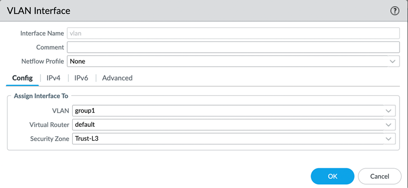
Figure 2.54: VLAN Interface configuration
You will also need to assign the VLAN interface an IP address that the clients on Layer 2 interfaces can use as a default gateway or routing next hop. Make sure it is in the same subnet as your clients on the Layer 2 interfaces:

Figure 2.55: VLAN Interface IP address
Besides Ethernet interfaces, there are also three different logical interfaces:
- Loopback
- Tunnel
- VLAN
We’ve covered VLAN interfaces and tunnel interfaces, so let’s now take a look at the Swiss army knife of interfaces, the loopback.
The loopback interface
A loopback interface is a logical Layer 3 interface that can serve many purposes. One common use case includes adding an additional public IP to its own interface so VPN configuration can be added to it. Another use case is to add a management profile to a loopback, and then leverage security rules to allow administrators to manage the firewall from exotic networks. It needs to be configured with an IP address (only a single IP per loopback interface is supported) and a security zone and it needs to be associated with a VR.
It can be set to a new IP address in the same subnet and zone as one of the Layer 3 interfaces, so services such as Management Profile, Captive Portal, and GlobalProtect can be hosted on a different IP than the main IP of the physical interface.
To add extra security, it can also be set to a different zone so that a matching security rule is needed for clients to be able to connect to the loopback interface:
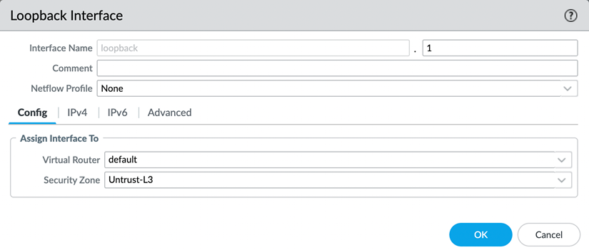
Figure 2.56: Loopback Interface
The number next to Interface Name is an identification number for the logical interface.
The tunnel interface
Tunnel interfaces are logical interfaces that serve as the ingress and egress point of tunneled traffic, both site-to-site VPN and GlobalProtect SSL and IPSec. The physical tunnel is terminated on a Layer 3 or loopback interface, but the packets that need to be encrypted should be routed to the tunnel interface:
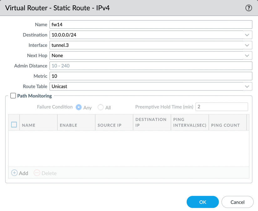
Figure 2.57: Static route for a VPN tunnel
This interface needs to be associated with a VR and a security zone, as you can see in the following screenshot:
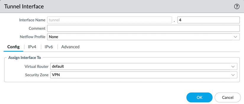
Figure 2.58: Tunnel Interface
The number next to Interface Name is an identification number for the logical interface.
Important note
For a strong security posture, set a separate zone for individual VPN connections, even for known locations. Treating each connection and remote network as an individual zone ensures adequate visibility and control. A remote office could be exposed to malware (think WannaCry) and infect other offices if the VPN tunnel is set to the same zone for all remote offices. The default intrazone security rule allows all sessions to run and does not apply scanning.
There are also several “special” interface types that provide a specific functionality; we’ll cover the special use case interfaces in the following sections.
When a switch uplink needs to contain multiple 802.1q VLAN tags, it can be configured as a trunk and, on the firewall, subinterfaces can be created to correspond to each VLAN tag.
Subinterfaces
All physical (that is, Layer 2, Layer 3, VWire, and Aggregate) interfaces can have subinterfaces. You can create these by selecting the desired physical interface and clicking on Add Subinterface at the bottom left of Network | Interfaces:
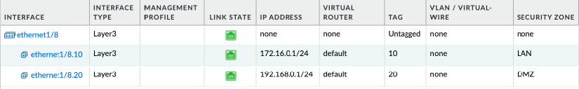
Figure 2.59: Creating a subinterface
A subinterface is used when the physical interface is connected to a trunked link containing VLAN (802.1Q) tagged packets. The physical interface is not able to interpret the tags, but subinterfaces are. For each VLAN carried by the trunk, you can create a subinterface to represent the virtual network coming from the switch. The advantage of using subinterfaces is that each VLAN can be associated with its own security zone.
The subinterface will mimic all the configuration specifics of its parent physical interface, but interface types cannot be different from the physical interface type (for example, a Layer 3 physical interface cannot host a Layer 2 subinterface).
HA interfaces
HA interfaces are required when setting up a cluster of two firewalls. Some chassis will have built-in dedicated HA interfaces, in which case you may not need to create any HA interfaces yourself. If no onboard HA interfaces are available, or additional interfaces are required to serve as backup HA links, data plane interfaces can be selected to fulfill this role and are connected to the HA peer.
AE interfaces
To increase available bandwidth above the physical limitations of the interfaces, interfaces can be bundled into an AE group using the 802.1AX protocol. Up to eight interfaces can be combined into a logical bundle.
A new group can be created by clicking on Add Aggregate Group under Network | Interfaces | Ethernet.
You first need to set the type to Layer 2, Layer 3, VWire, or HA, which will require the same configuration as the physical interface equivalent (that is, security zone, VR, or VLAN or VWire).
Additionally, you can configure the Link Aggregation Control Protocol (LACP) to improve interface failure detection. LACP enables link failure detection on the physical and data link layer, while the default protocol only detects physical link failure.
You can set whether the firewall is in Active or Passive mode. This configuration setting needs to be reviewed with the LACP peer (typically the switch) as only one peer can be configured as Active, but LACP will not work if both are set to Passive.
The transmission rate will have an impact on the responsiveness of link failure detection, but it will also have an overhead. Slow transmission means every 30 seconds, while fast transmission means every second.
Fast Failover will fail to an operational interface within 1 second when an interface goes down. Traditional failover happens after 3 seconds.
System Priority determines which peer determines port priorities.
Maximum Interfaces determines how many interfaces can be active at the same time within the aggregate group. This number should not exceed the number of physical interfaces you assign to the group, but can be leveraged to limit total available bandwidth while keeping hot interfaces in reserve in case of failure. (For example, if a total bandwidth of 4 gigabits is needed for an aggregate group, but you also do not want to exceed this bandwidth to preserve system resources, you can assign five or more interfaces to the aggregate group, and set Maximum Interfaces to 4. Only when an interface fails will another one be activated to pick up the work.) In a high-availability configuration where two firewalls form a cluster, LACP can be enabled on the passive peer so the link aggregation group is prenegotiated before the passive peer needs to assume an active role, which cuts down on the time needed to failover.
This is achieved by checking Enable in HA Passive State. The same system MAC can be used on both cluster members, but this may not be supported by the connected switches.
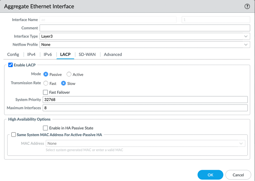
Figure 2.60: Link Aggregation Control Protocol
When the Aggregate Group is created, you can add the interfaces by setting the Interface Type to Aggregate Ethernet and selecting the desired Aggregate Group:
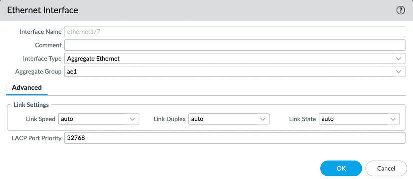
Figure 2.61: A physical interface in an aggregate group
In some cases, you may need to be able to connect to a port mirror on a switch and just listen without participating. For such instances, you can configure a tap interface.
Tap interfaces
Tap interfaces can be used as a passive sniffing port. If a different network device is set up with port mirroring, its egress port can be connected to the tap interface to intercept all packets and apply the app ID and content ID. As long as the tap interface is sent all packets of a session, it will be able to inspect the traffic as if it is flowing through the firewall. There are, however, a few limitations:
- As the firewall is not actively participating in the processing of packets, it cannot take action if it detects a threat; it can only report it.
- SSL decryption can only be applied to inbound connections if the server certificate can be loaded onto the firewall with its private key.
The tap interface only needs to be configured with a security zone:
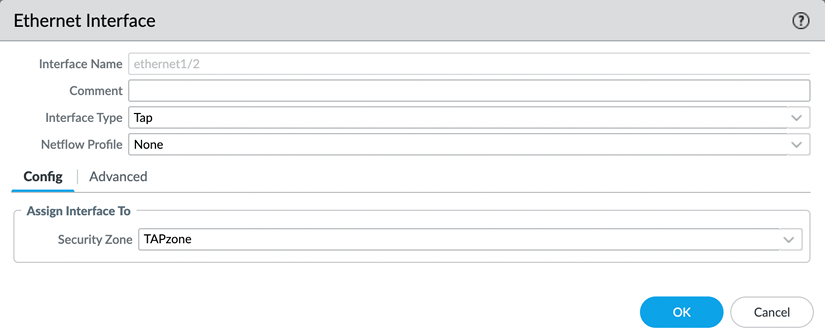
Figure 2.62: The tap interface
To optimally benefit from the tap functionality, a security rule will need to be created that allows all operations, or a specific subset, if you want to limit the scope. The firewall will discard all packets in the background, but setting the security rule to drop would discard the packets before inspection:

Figure 2.63: The tap security rule
Similar to listening in on a port mirror, the firewall can send all unencrypted session data to a third-party DLP (Data Loss Prevention) or threat intelligence device. It can do so via a Decryption Port Mirror interface.
The Decryption Port Mirror interface
The Decryption Port Mirror interface allows the forwarding of decrypted packets to an external device for further inspection. This can be useful for data loss prevention, for example. The license can be activated for free via the support portal by browsing to https://support.paloaltonetworks.com and then going to Assets | Devices.
There, you can find your firewall and click the Actions button. If you choose to activate a feature license, you will be able to activate Decryption Port Mirror:
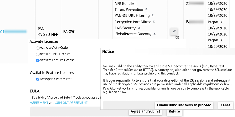
Figure 2.64: Activating a Decryption Port Mirror license
To activate the license on the firewall, follow these steps:
- From Device | Licenses, select Retrieve license keys from license server
- In Device | Setup | Content ID | Content-ID settings, enable Allow forwarding of decrypted content
- In Network | Interfaces | Ethernet, set an interface to the Decrypt Mirror type
- In Objects | Decryption | Decryption Profiles, open the decryption profile and add the interface to Decryption Mirroring
- In Policies | Decryption, create decryption rules that use the decryption profile
- Save the changes and connect the Decryption Port Mirror interface
With the information covered in the last sections you are now able to select the appropriate interface for each network design you may come across. VWire helps you add a firewall in an environment where you can’t interfere with existing routing, Layer 3 interfaces put the firewall in the middle of routing decisions, Layer 2 interfaces make the firewall act in a similar way a switch would, and subinterfaces can be added to all of these to account for VLAN tags. You are able to configure link aggregation and can leverage tunnel interfaces to set up IPSec tunnels.