Book Image

Learning PostgreSQL 11 - Third Edition

By : Salahaldin Juba, Andrey Volkov
Book Image

Learning PostgreSQL 11 - Third Edition

By: Salahaldin Juba, Andrey Volkov

Overview of this book

PostgreSQL is one of the most popular open source database management systems in the world, and it supports advanced features included in SQL standards. This book will familiarize you with the latest features in PostgreSQL 11, and get you up and running with building efficient PostgreSQL database solutions from scratch. Learning PostgreSQL, 11 begins by covering the concepts of relational databases and their core principles. You’ll explore the Data Definition Language (DDL) and commonly used DDL commands supported by ANSI SQL. You’ll also learn how to create tables, define integrity constraints, build indexes, and set up views and other schema objects. As you advance, you’ll come to understand Data Manipulation Language (DML) and server-side programming capabilities using PL/pgSQL, giving you a robust background to develop, tune, test, and troubleshoot your database application. The book will guide you in exploring NoSQL capabilities and connecting to your database to manipulate data objects. You’ll get to grips with using data warehousing in analytical solutions and reports, and scaling the database for high availability and performance. By the end of this book, you’ll have gained a thorough understanding of PostgreSQL 11 and developed the necessary skills to build efficient database solutions.
Table of Contents (18 chapters)

Data modeling

Data models describe real-world entities such as customer, service, products, and the relation between these entities. Data models provide an abstraction for the relations in the database. Data models aid the developers in modeling business requirements and translating business requirements to relations. They are also used for the exchange of information between the developers and business owners.

In the enterprise, data models play a very important role in achieving data consistency across interacting systems. For example, if an entity is not defined, or is poorly defined, then this will lead to inconsistent and misinterpreted data across the enterprise. For instance, if the semantics of the customer entity are not defined clearly, and different business departments use different names for the same entity such as customer and client, this may lead to confusion in the operational departments.

Data model perspectives

Data model perspectives are defined by ANSI as follows:

  • Conceptual data model: Describes the domain semantics, and is used to communicate the main business rules, actors, and concepts. It describes the business requirements at a high level and is often called a high-level data model.
  • Logical data model: Describes the semantics for a certain technology, for example, the UML class diagram for object-oriented languages.
  • Physical data model: Describes how data is actually stored and manipulated at the hardware level, such as storage area network, table space, CPUs, and so on.

According to ANSI, this abstraction allows changing one part of the three perspectives without amending the other parts. One could change both the logical and the physical data models without changing the conceptual model. To explain, sorting data using bubble or quick sort is not of interest for the conceptual data model. Also, changing the structure of the relations could be transparent to the conceptual model. One could split one relation into many relations after applying normalization rules, or by using enum data types in order to model the lookup tables.

The entity-relation model

The entity-relation (ER) model falls into the conceptual data model category. It captures and represents the data model for both business users and developers. The ER model can be transformed into the relational model by following certain techniques.

Conceptual modeling is a part of the software development life cycle (SDLC). It is normally done after the functional and data requirement-gathering stage. At this point, the developer is able to make the first draft of the ER diagram as well as describe functional requirements using data flow diagrams, sequence diagrams, user stories, and many other techniques.

During the design phase, the database developer should give great attention to the design, run a benchmark stack to ensure performance, and validate user requirements. Developers modeling simple systems could start coding directly. However, care should be taken when making the design, since data modeling involves not only algorithms in modeling the application but also data. The change in design might lead to a lot of complexities in the future such as data migration from one data structure to another.

While designing a database schema, avoiding design pitfalls is not enough. There are alternative designs where one could be chosen. The following pitfalls should be avoided:

  • Data redundancy: Bad database designs elicit redundant data. Redundant data can cause several other problems, including data inconsistency and performance degradation. When updating a tuple that contains redundant data, the changes on the redundant data should be reflected in all the tuples that contain this data.
  • Null saturation: By nature, some applications have sparse data, such as medical applications. Imagine a relation called diagnostics, which has hundreds of attributes for symptoms such as fever, headache, sneezing, and so on. Most of them are not valid for certain diagnostics, but they are valid in general. This could be modeled by utilizing complex data types such as JSON.
  • Tight coupling: In some cases, tight coupling leads to complex and difficult-to-change data structures. Since business requirements change with time, some requirements might become obsolete. Modeling generalization and specialization (for example, a part-time student is a student) in a tightly coupled way may cause problems.

Sample application

In order to explain the basics of the ER model, an online web portal to buy and sell cars will be modeled. The requirements of this sample application are as follows, and an ER model will be developed step by step:

  1. The portal provides the facility to register users online and provides different services for users based on their categories.
  2. Users might be sellers or normal users. The sellers can create new car advertisements; other users can explore and search for cars.
  3. All users should provide their full name and a valid email address during registration. The email address will be used for logging in.
  4. The seller should also provide an address.
  1. The user can rate the advertisement and the seller's service quality.
  2. All users' search history should be maintained for later use.
  3. The sellers have ranks and this affects the advertisement search; the rank is determined by the number of posted advertisements and the user's rank.
  4. The car advertisement has a date and the car can have many attributes such as color, number of doors, number of previous owners, registration number, pictures, and so on.

Entities, attributes, and keys

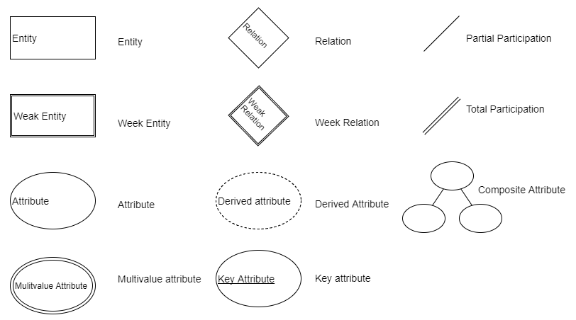
The ER diagram represents entities, attributes, and relationships. An entity is a representation of a real-world object such as a car or a user. An attribute is a property of an object and describes it. A relationship represents an association between two or more entities.

The attributes might be composite or simple (atomic). Composite attributes can be divided into smaller subparts. A subpart of a composite attribute provides incomplete information that is semantically not useful by itself. For example, the address is composed of a street name, building number, and postal code. Any one of them isn't useful alone, without its counterparts.

Attributes could also be single-valued or multi-valued. The color of a bird is an example of a multi-valued attribute. It can be red and black, or a combination of any other colors. A multi-valued attribute can have a lower and upper bound to constrain the number of values allowed. In addition, some attributes can be derived from other attributes. Age can be derived from the birth date. In our example, the final rank of a seller is derived from the number of advertisements and the user ratings.

Key attributes can identify an entity in the real world. A key attribute should be marked as a unique attribute, but not necessarily as a primary key, when physically modeling the relation. Finally, several attribute types could be grouped together to form a complex attribute:

Entities should have a name and a set of attributes. They are classified into the following:

  • Weak entity: Does not have key attributes of its own
  • Strong entity/regular entity: Has a key attribute

A weak entity is usually related to a strong entity. This strong entity is called the identifying entity. Weak entities have a partial key, also known as a discriminator, which is an attribute that can uniquely identify the weak entity, and it is related to the identifying entity. In our example, if we assume that the search key is distinct each time the user searches for cars, then the search key is the partial key. The weak entity symbol is distinguished by surrounding the entity box with a double line.

The following diagram shows the preliminary design of a car portal application. The user entity has several attributes. The name attribute is a composite attribute, and email is a key attribute. The seller entity is a specialization of the user entity. The total rank is a derived attribute calculated by aggregating the user ratings and the number of advertisements. The color attribute of the car is multi-valued. The seller can be rated by the users for certain advertisements; this relation is a ternary relation, because the rating involves three entities, which are car, seller, and user.

The car picture is a subpart attribute of the advertisement. The following diagram shows that the car can be advertised more than once by different sellers. In the real world, this makes sense, because one could ask more than one seller to sell his car:

When an attribute of one entity refers to another entity, some relationships exist. In the ER model, these references should not be modeled as attributes but as relationships or weak entities. Similar to entities, there are two classes of relationships: weak and strong. Weak relationships associate the weak entities with other entities. Relationships can have attributes as entities. In our example, the car is advertised by the seller; the advertisement date is a property of the relationship.

Relationships have cardinality constraints to limit the possible combinations of entities that participate in a relationship. The cardinality constraint of car and seller is 1:N; the car is advertised by one seller, and the seller can advertise many cars. The participation between seller and user is called total participation, and is denoted by a double line. This means that a seller cannot exist alone, and he must be a user.

The many-to-many relationship cardinality constraint is denoted by N:M to emphasize the different participation by the entities.

Up until now, only the basic concepts of ER diagrams have been covered. Some concepts, such as (min, max) cardinality notation, ternary/n-ary relationships, generalization, specialization, and enhanced entity relation (EER) diagrams, have not been discussed.

Mapping ER to relations

The rules to map an ER diagram to a set of relations (that is, the database schema) are almost straightforward, but not rigid. One could model an entity as an attribute, and then refine it to a relationship. An attribute that belongs to several entities can be promoted to be an independent entity. The most common rules are as follows (note that only basic rules have been covered, and the list is not exhaustive):

  • Map regular entities to relations. If entities have composite attributes, then include all the subparts of the attributes. Pick one of the key attributes as a primary key.
  • Map weak entities to relations. Include simple attributes and the subparts of the composite attributes. Add a foreign key to reference the identifying entity. The primary key is normally the combination of the partial key and the foreign key.
  • If a relationship has an attribute and the relation cardinality is 1:1, then the relation attribute can be assigned to one of the participating entities.
  • If a relationship has an attribute and the relation cardinality is 1:N, then the relation attribute can be assigned to the participating entity on the N side.
  • Map many-to-many relationships, also known as N:M, to a new relation. Add foreign keys to reference the participating entities. The primary key is the composition of foreign keys.
  • Map a multi-valued attribute to a relation. Add a foreign key to reference the entity that owns the multi-valued attribute. The primary key is the composition of the foreign key and the multi-valued attribute.

UML class diagrams

Unified Modeling Language (UML) is a standard developed by the Object Management Group (OMG). UML diagrams are widely used in modeling software solutions, and there are several types of UML diagrams for different modeling purposes including class, use case, activity, and implementation diagrams.

A class diagram can represent several types of associations, that is, the relationship between classes. They can depict attributes as well as methods. An ER diagram can be easily translated into a UML class diagram. UML class diagrams also have the following advantages:

  • Code reverse-engineering: The database schema can be easily reversed to generate a UML class diagram.
  • Modeling extended relational database objects: Modern relational databases have several object types such as sequences, views, indexes, functions, and stored procedures. UML class diagrams have the capability to represent these object types.

The following class diagram is generated from reverse-engineering the SQL code of a car_portal database: