

Implementing an LED status indicator on the breadboard
We have the chance to interact with the world around us with microcontrollers. For example, we can get data from sensors or perform physical actions, such as turning on and off an LED or moving an actuator.
In this recipe, we will learn how to connect external components with the microcontroller by building the following electronic circuit on the breadboard:
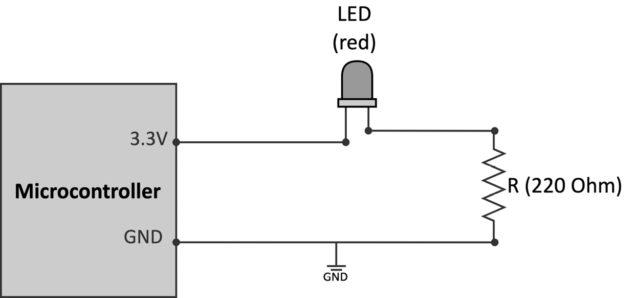
Figure 2.4 – LED power status indicator circuit
The preceding circuit uses a red LED to indicate whether the microcontroller is plugged into the power.
Getting ready
When connecting external components to the microcontroller, we mean physically joining two or more metal connectors together. Although we could solder these connectors, it is not usual for prototyping because it is not quick and straightforward.
Therefore, this Getting ready section aims to present a solderless alternative to connect our components effortlessly.
Making contacts directly with the microcontroller's pins can be extremely hard for the tiny space between each pin. For example, considering the RP2040 microcontroller, the pin space is roughly 0.5 mm since the chip size is 7x7 mm. Therefore, it would be practically impossible to connect any of our components safely since most terminals have a wire diameter of ~1 mm.
For this reason, our platforms provide alternative points of contact with wider spacing on the board. These contact points on the Arduino Nano and Raspberry Pi Pico are the two rows of pre-drilled holes located at the platform's edge.
The simplest way to know the correspondence between these contacts and the microcontroller pins is to refer to the datasheet of the microcontroller boards. Hardware vendors usually provide the pinout diagram to note the pins' arrangement and functionality.
For example, the following list reports the links to the Arduino Nano and Raspberry Pi Pico pinout diagrams:
- Arduino Nano:
https://content.arduino.cc/assets/Pinout-NANOsense_latest.pdf
- Rasberry Pi Pico:
https://datasheets.raspberrypi.org/pico/Pico-R3-A4-Pinout.pdf
On top of these pre-drilled holes, which often come with a 2.54 mm spacing, we can solder a header to insert and connect the electronic components easily.
The header can be either a male (pin header) or a female connector (socket header), as shown in the following figure:
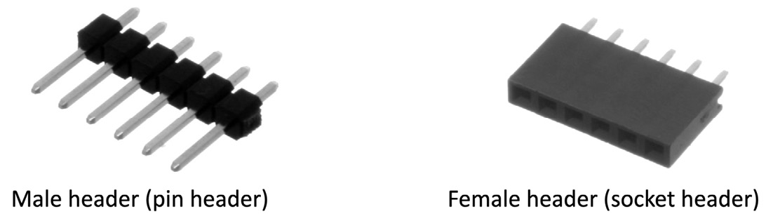
Figure 2.5 – Male header versus female header (image from https://en.wikipedia.org/wiki/Pin_header)
Important Note
We recommend buying devices with pre-soldered male headers if you are not familiar with soldering or just want a ready-to-go solution.
As we have seen, the boards provide a way to connect the external components with the microcontroller. However, how can we attach other electrical elements to build a complete electronic circuit?
Prototyping on a breadboard
The breadboard is a solderless prototyping platform to build circuits by pushing the device's pins in a rectangular grid of metal holes:
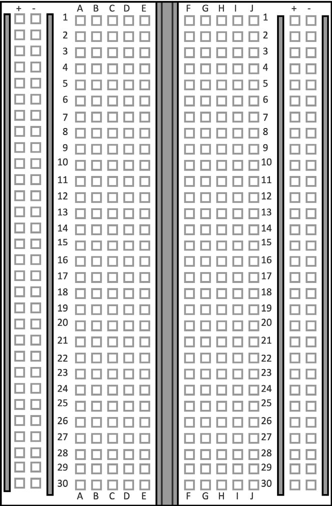
Figure 2.6 – Solderless breadboard
As shown in the previous figure, breadboards provide two connecting areas for our components:
- Bus rails are usually located on both sides of the breadboard and consist of two columns of holes identified with the symbols + and – as shown in the following diagram:
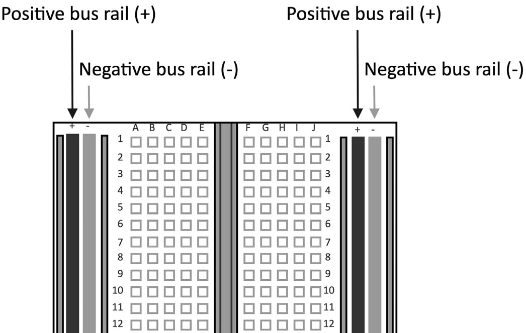
Figure 2.7 – Bus rails labeled with + and - on both sides of the breadboard
All the holes of the same column are internally connected. Therefore, we will have the same voltage through all its columns when applying a voltage to whatever hole.
Since bus rails are beneficial for having reference voltages for our circuits, we should never apply different voltages on the same bus column.
- Terminal strips are located in the central area of the breadboard and join only the holes of the same row so that the following occurs:
- Holes on the same row have the same voltage.
- Holes on the same column might have a different voltage.
However, since we typically have a notch running parallel in the middle of the breadboard, we have two different terminal strips per row, as shown in the following figure:
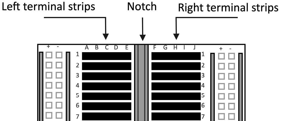
Figure 2.8 – Terminal strips are located in the central area of the breadboard
We can place several devices on the breadboard and connect them through jumper wires.
Note
The size of a breadboard is defined by the number of rows and columns in the terminal area. In our case, we will always refer to a half-sized breadboard with 30 rows and 10 columns.
How to do it...
Before building any circuits, unplug the micro-USB cable from the microcontroller board to remove the possibility of unintentionally damaging any components.
Once we have disconnected the board from the power, follow the following steps to build the circuit to turn the LED on when the platform is plugged into the power:
- Put the microcontroller board on the breadboard:
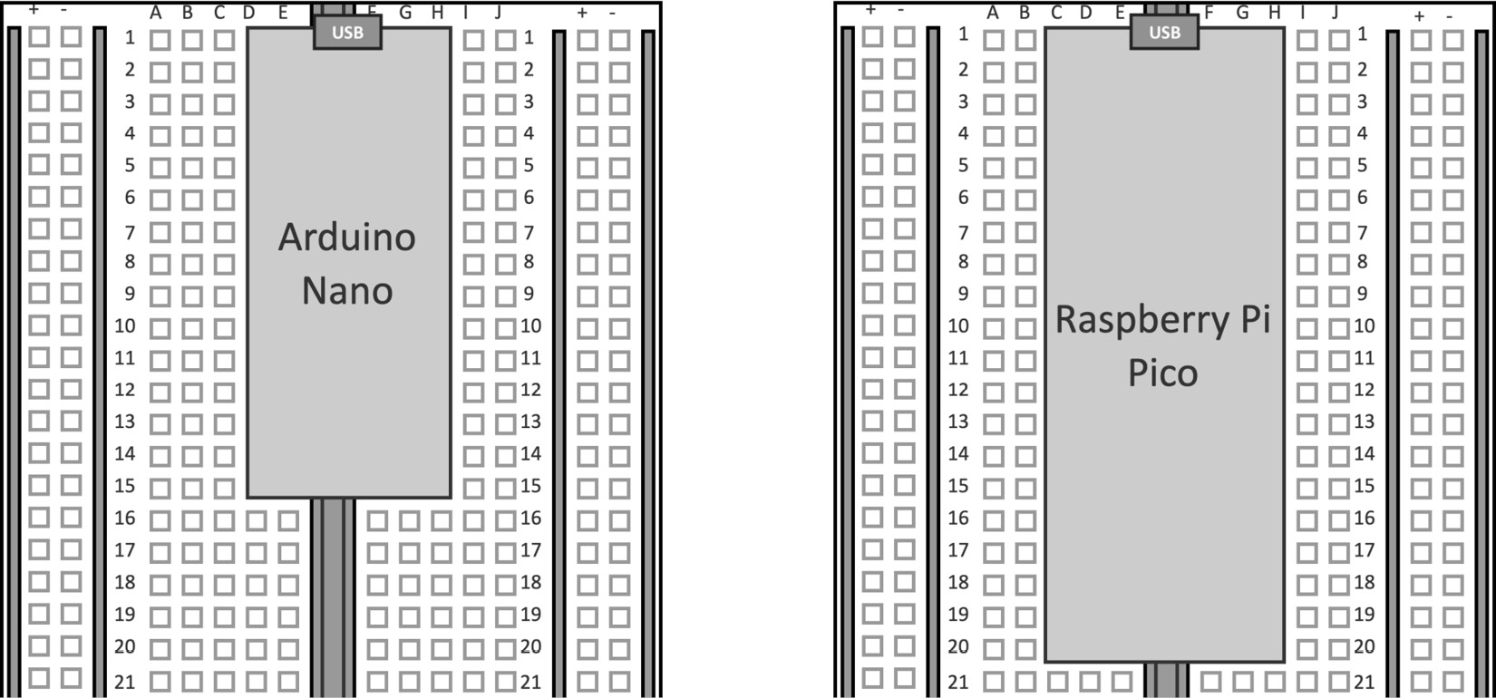
Figure 2.9 – Vertically mount the microcontroller board between the left and right terminal strips
Since we have a notch running parallel, it is safe to put the platforms in this way because the left and right pin headers touch two different terminal strips.
- Use two jumper wires to connect the 3.3 V and GND pins of the microcontroller board with the + and - bus rails:
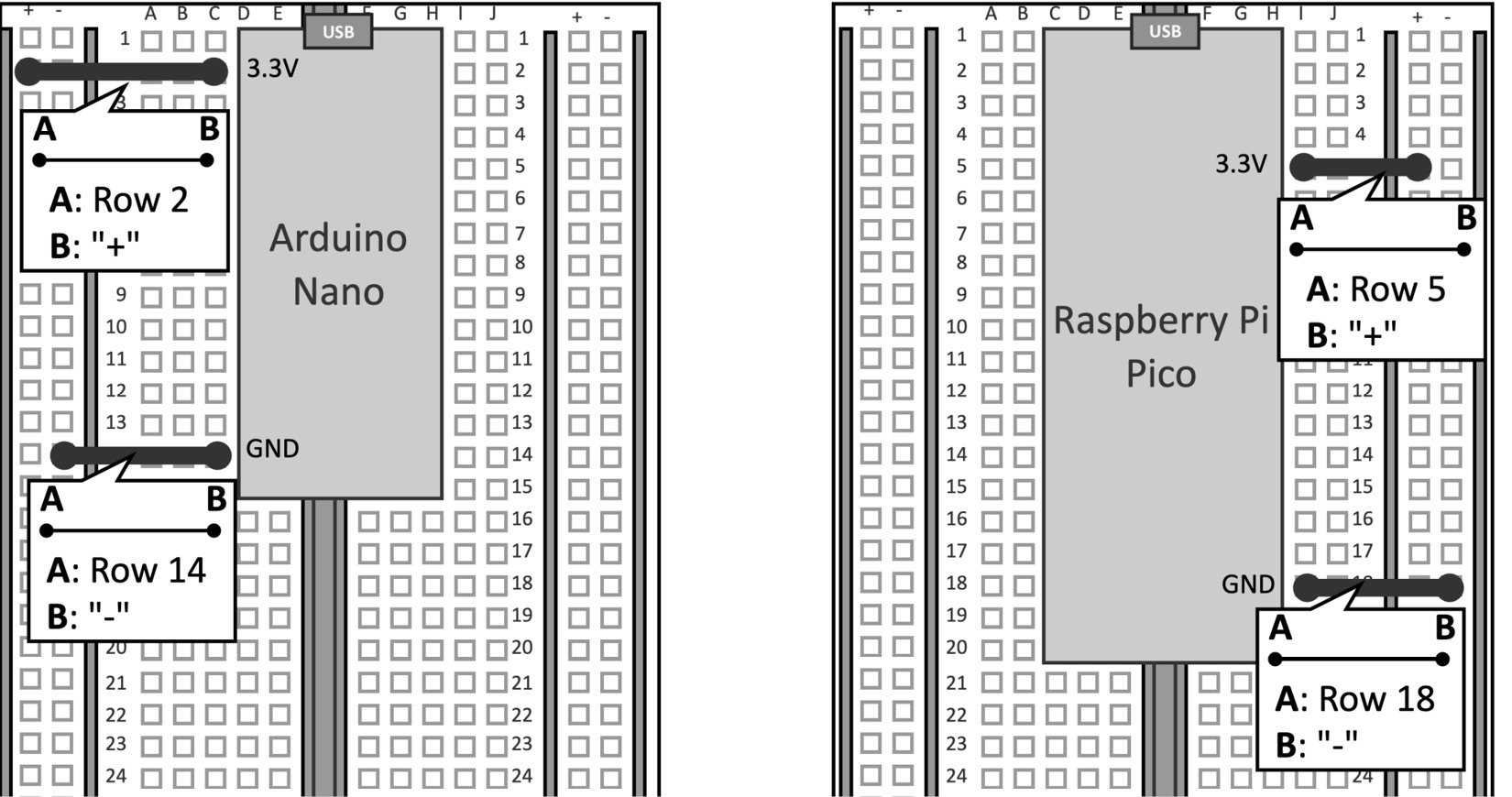
Figure 2.10 – Use the jumper wires to connect the 3.3 V and GND to the + and - bus rails
It is important to note that all holes of the bus rails will have 3.3 V and GND, respectively, only when the microcontroller is connected to the power.
- Insert the LED pins on two terminal strips:
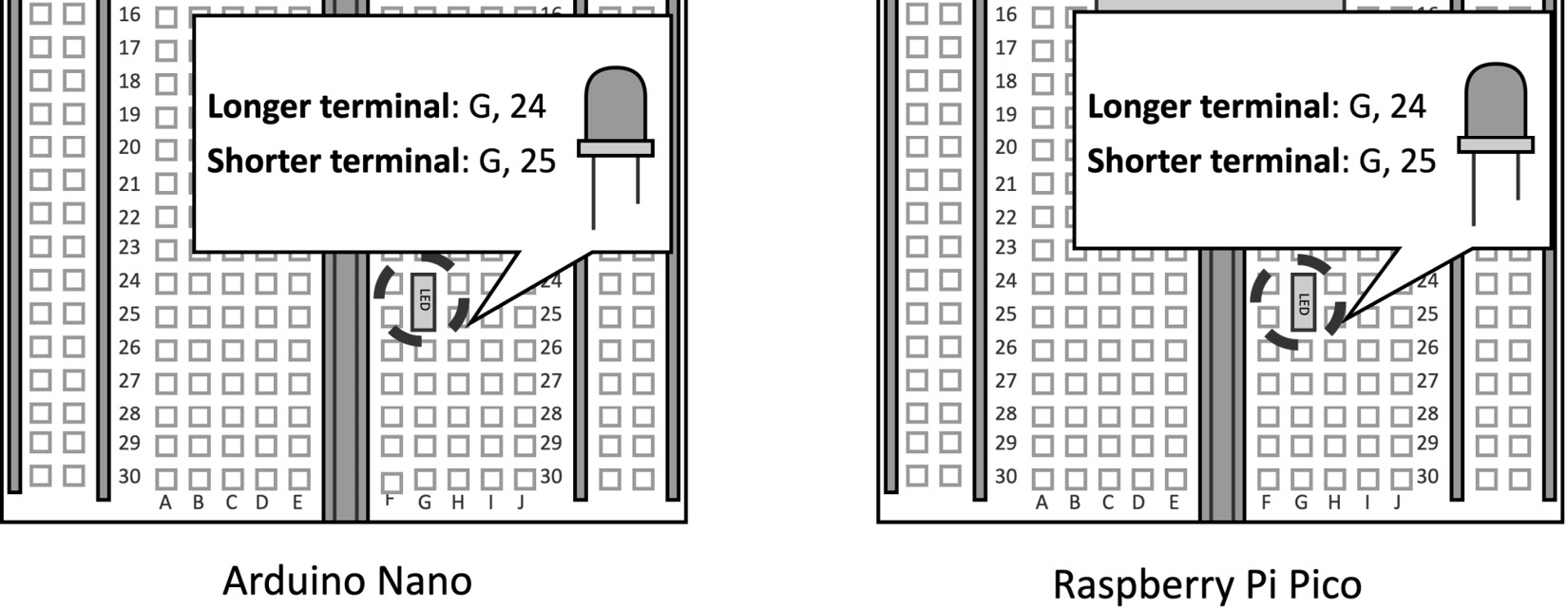
Figure 2.11 – Insert the LED on the breadboard
In the preceding figure, we insert the longer LED terminal in (H, 24) and the shorter one in (H, 25). Do not invert the longer and shorter terminals because then the LED won't turn on.
- Place the 220 Ω resistor in series with the LED:
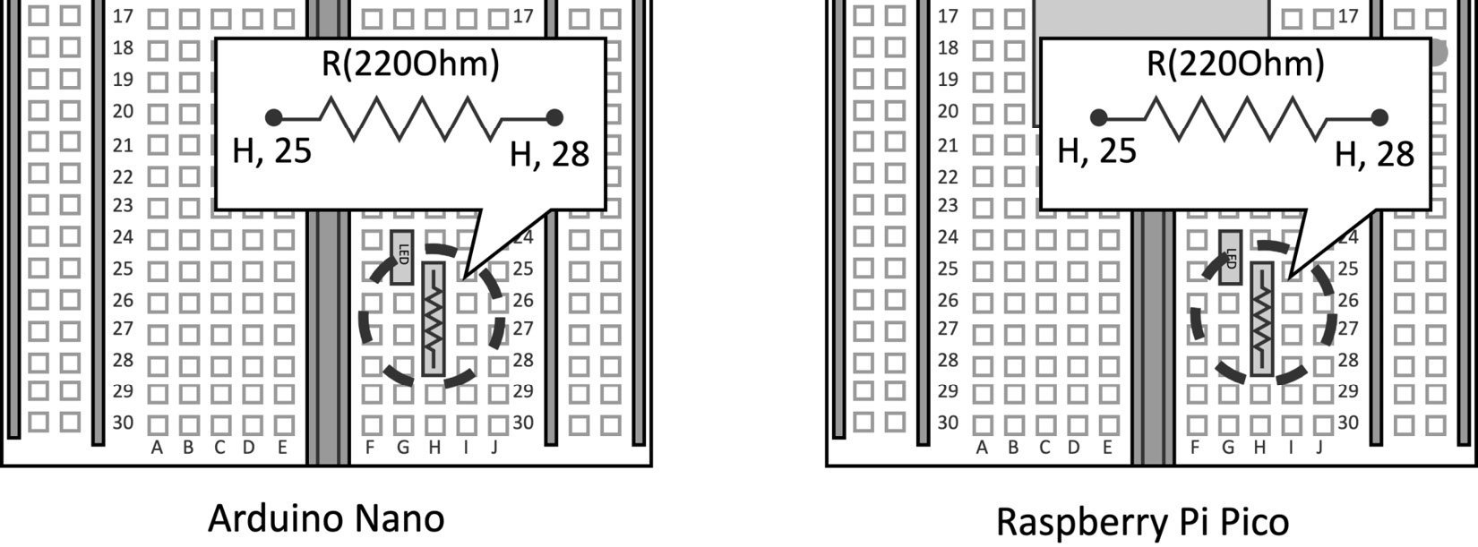
Figure 2.12 – Place the resistor in series with the LED
The color bands of the resistor can be determined through the Digikey web tool (https://www.digikey.com/en/resources/conversion-calculators/conversion-calculator-resistor-color-code). For example, a 220Ω resistor with five or six bands is encoded with the following colors:
- First band: red (2)
- Second band: red (2)
- Third band: black (0)
- Fourth band: black (1)
As reported in the circuit presented at the beginning of this recipe, one terminal of the resistor should touch the shorter LED pin. In our case, we insert one terminal in (H, 25). The remaining terminal of the resistor goes in whichever unused terminal strip. In our case, we insert this terminal in (H, 28).
- Close the circuit by connecting the + bus rail (3.3 V) to the longer LED pin and the - bus rail (GND) to the resistor terminal:
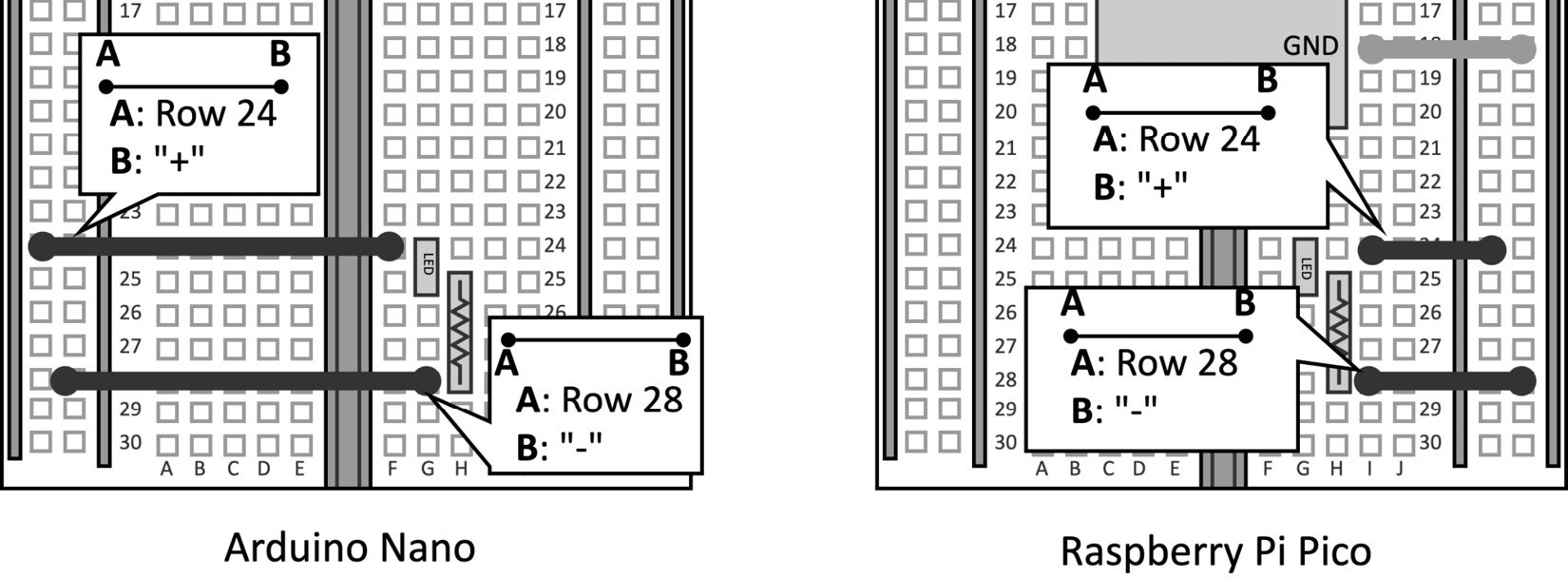
Figure 2.13 – Close the circuit by connecting 3.3 V and GND
The previous figure shows how to connect the two remaining jumper wires used to close the circuit. One jumper wire connects the + bus rail with the longer LED terminal (H, 24) while the other one connects the - bus rail with the resistor (H, 28).
Now, the LED should emit light whenever you plug the microcontroller into the power with the micro-USB cable.