

Turning an LED on and off with a push-button
In contrast to a PC where the keyboard, mouse, or even a touchscreen facilitates human interactions with the software applications, a physical button represents the easiest way for a user to interact with a microcontroller.
This recipe will teach us how to program the GPIO to read the status of a push-button (pushed or released) to control the LED light.
The following Arduino sketch contains the code referred to in this recipe:
04_gpio_in_out.ino:
Getting ready
To get ready for this recipe, we need to know how this device works and program the GPIO peripheral in input mode.
The push-button is a type of button used with microcontrollers, and it has boolean behavior since its state can either be pushed (true) or released (false).
From an electronics point of view, a push-button is a device that makes (a.k.a. short) or breaks (a.k.a. open) the connection between two wires. When we press the button, we connect the wires through a mechanical system, allowing the current to flow. However, it is not like a standard light switch that keeps the wires connected when released. When we don't apply pressure to the button, the wires disconnect, and the current stops flowing.
Although this device has four metal legs, it is a two-terminal device because the contacts on the opposite side (1, 4 and 2, 3) are connected, as shown in the following figure:
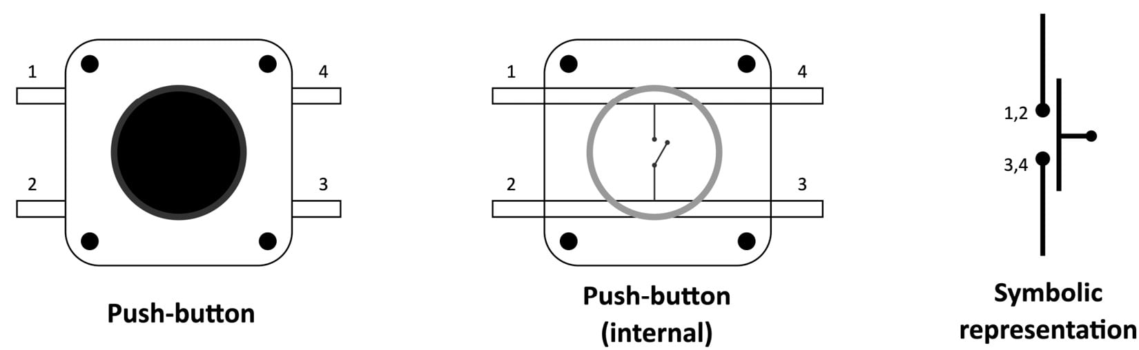
Figure 2.26 – Push-button representation
When building a circuit with this component, the legs on the same side (1,2 or 4,3 in the preceding figure) are responsible for connecting two points. These two points will have the same voltage when the push-button is pressed.
The state of a push-button can be read with the GPIO peripheral in input mode. When configuring the GPIO in input mode, the peripheral reads the applied voltage on the pin to infer the logical level. From this value, we can guess whether the button is pressed.
In the following diagram, the voltage on the GPIO pin is GND when we press the button. However, what is the voltage when the button is released?
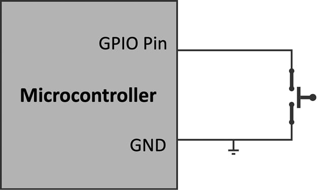
Figure 2.27 – What is the voltage on the GPIO pin when we release the push-button?
Although the pin could only assume two logical levels, this could not be true in some input mode circumstances. A third logical level called floating (or high impedance) could occur if we do not take circuit precautions. When the floating state occurs, the pin's logical level is undefined because the voltage fluctuates between 3.3 V and GND. Since the voltage is not constant, we cannot know whether the push-button is pressed. To prevent this problem, we must include a resistor in our circuit to always have a well-defined logical level under all conditions.
Depending on what logical level we want in the pushed state, the resistor can be as follows:
- Pull-up: The resistor connects the GPIO pin to the 3.3 V. Thus, the GPIO pin reads LOW in the pushed state and HIGH in the released state.
- Pull-down: The resistor connects the GPIO pin to GND in contrast to the pull-up configuration. Thus, the GPIO pin reads the logical level HIGH in the pushed state and LOW in the released state.
The following diagram shows the difference between the pull-up and pull-down configurations:
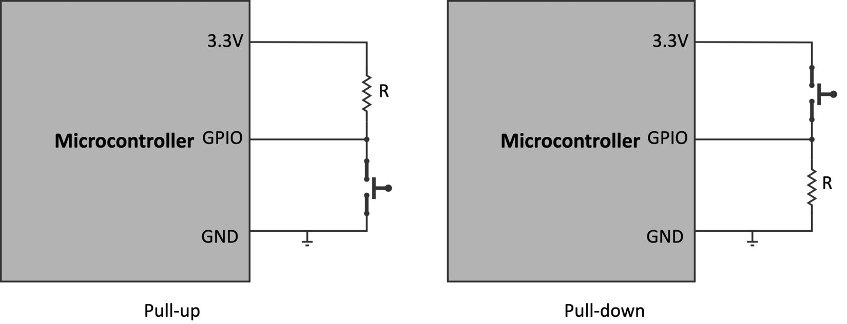
Figure 2.28 – Pull-up versus pull-down configurations
Typically, a 10 K resistor should be okay for both cases. However, most microcontrollers offer an internal and programmable pull-up resistor so the external one is often not needed.
How to do it...
Keep all the components on the breadboard. The following steps will show what to change in the previous sketch to control the LED status with the push-button:
- Choose the GPIO pin for reading the push-button state. The following table reports our choice.
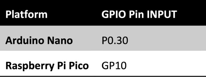
Figure 2.29 – GPIO pin used to read the push-button state
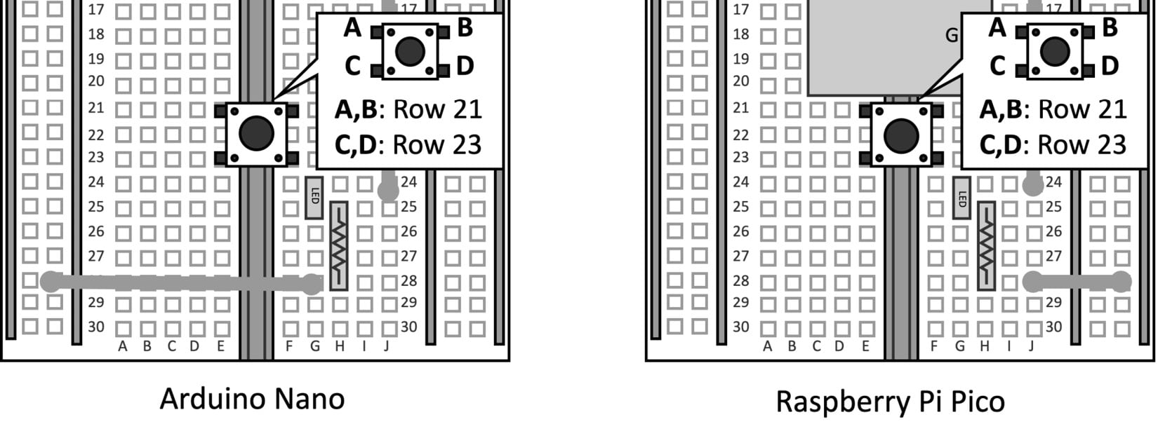
Figure 2.30 – The push-button is mounted between the terminal strips 21 and 23
As we can observe from the preceding diagram, we use terminal strips not employed by other devices.
- Connect the push-button to the GPIO pin and GND:
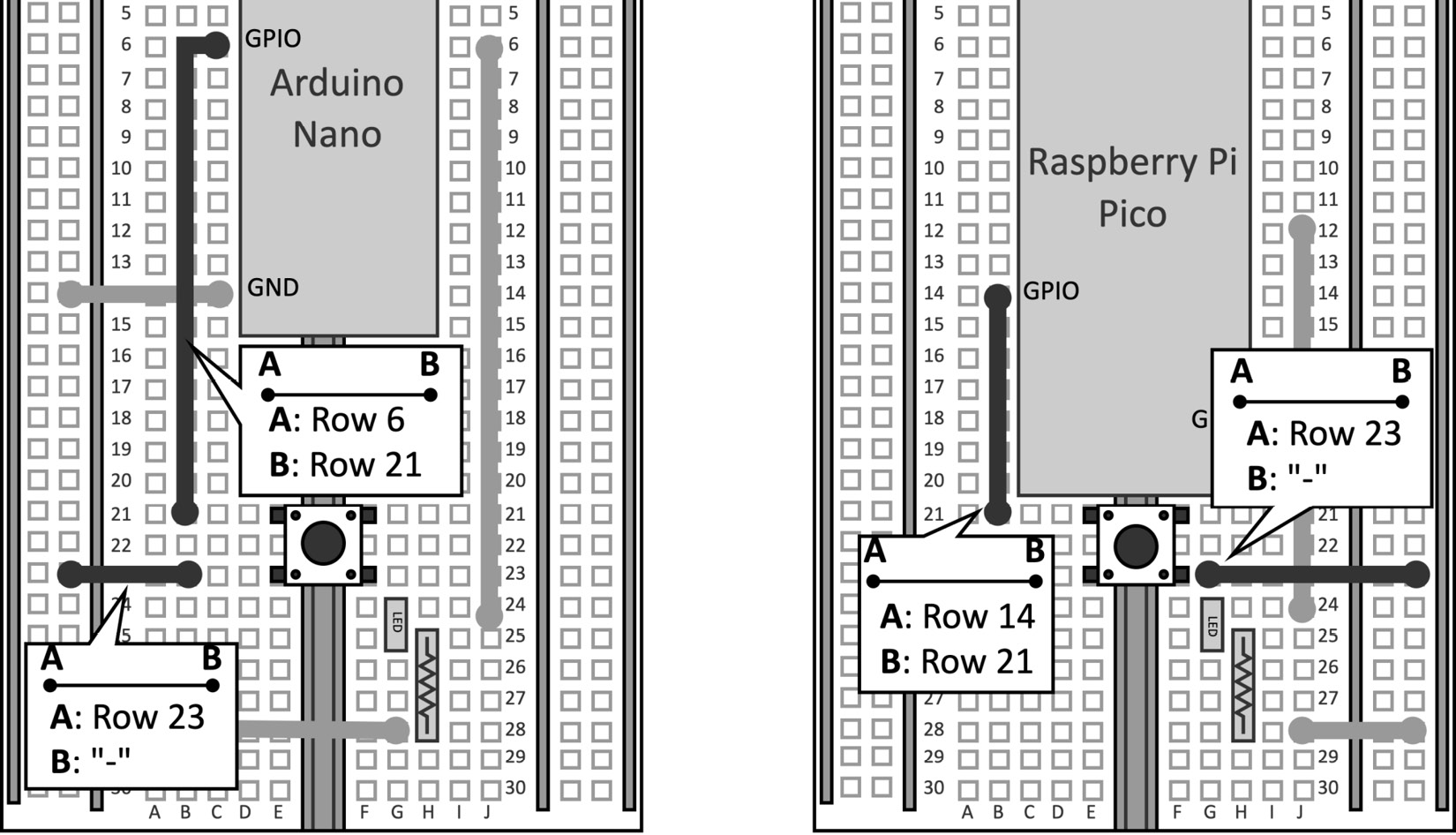
Figure 2.31 – The push-button is only connected to the GPIO pin and GND
The floating state will not occur because we use the microcontroller pull-up resistor.
- Open the sketch developed in the previous recipe. Declare and initialize a global
mbed::DigitalInobject with the pin name used for the push-button.
For the Arduino Nano:
mbed::DigitalIn button(p30);
And this for the Raspberry Pi Pico:
mbed::DigitalIn button(p10);
mbed::DigitalIn (https://os.mbed.com/docs/mbed-os/v6.15/apis/digitalin.html) is used to interface with the GPIO peripheral in input mode. The initialization only requires the GPIO pin (PinName) connected to the push-button.
- Set the button mode to
PullUpin thesetup()function:void setup() { button.mode(PullUp); }
The preceding code enables the microcontroller's internal pull-up resistor.
- Turn on the LED when the push-button is LOW (0) in the
loop()function:void loop() { led = !button; }
We just need to set the led object to the opposite value returned by button to light up the LED when the push-button is pressed.
Compile the sketch and upload the program to the microcontroller.
Tip
When the push-button is pressed, the switch could generate spurious logical-level transitions due to the mechanical nature of the component. This issue is called button bouncing because the switch response bounces between HIGH and LOW for a short time. You may consider adopting a switch debouncing algorithm (for example, https://os.mbed.com/teams/TVZ-Mechatronics-Team/wiki/Timers-interrupts-and-tasks) to prevent the generation of multiple transitions.