
Nowadays, it can be assumed that almost any architect or architectural office use CAD or modeling software, such as Autodesk AutoCAD or Nemetschek VectorWorks, commonly in combination with Trimble SketchUp . In addition, we currently see a migration towards Building Information Modeling (BIM), which will be discussed in the next section.
It should be noted that 2D Drafting is still omnipresent in architectural offices worldwide. While AutoCAD presents both 2D and 3D functionality, many offices still rely on the creation of 2D documents for documentation purposes. The first hurdle they need to tackle in the context of real-time architectural visualization is switching to 3D, as the use of a Game Authoring Environment, such as Unity makes hardly any sense when you don't create 3D models.
As it stands, Unity is mostly oriented to the so-called Digital Content Creation (DCC) systems, which provide a combination of modeling, rendering, and animation functionality, such as Autodesk 3ds Max
or
Maxon CINEMA 4D. Models from such software can be saved directly inside the Unity project's Assets folder and are subsequently converted in the background automatically. When using any of the directly supported software tools, modelers can further edit the models by simply double-clicking the model name from within Unity. This opens the original software, where they can modify the model and save it again, with Unity taking care of the model conversion in the background. This approach is supported by Autodesk 3ds Max and Maya, Maxon CINEMA 4D, Blender, and some other applications given at http://docs.unity3d.com/Documentation/Manual/3D-formats.html. However, most architects will agree that these are not the primary modeling systems in use for architectural modeling.
As it stands, a typical CAD model in for example, AutoCAD DWG format, is not supported by Unity, so you need to convert your model into an alternative format. The FBX format is currently the best supported format for Unity, probably alongside the open COLLADA format, with extension .DAE. If your CAD or 3D software can export one of these two formats directly, use them as your first choice. Otherwise, you can try if your software has 3DS or OBJ export, which are the other two formats that Unity can also read directly. While DXF is supported as well, this is not recommended, as you need to use an older version of the format and texture information will not survive the conversion.
The following table gives an overview of which formats can be exported from some typical CAD software into Unity 4.x and also discusses expected possible problems.
|
CAD Software |
Export |
Comments |
|---|---|---|
|
AutoCAD ( |
|
Not supported by Unity. |
|
|
Not recommended. | |
|
|
Preferred, especially if textures have been applied already. | |
|
VectorWorks ( |
|
Not recommended. |
|
|
Exchange add-on recommended; requires CINEMA 4D. | |
|
|
RenderWorks add-on required. | |
|
SketchUp ( |
|
Preferred, but only supported by Pro-version or add-ins. |
|
|
Through Google Earth | |
|
|
Can be added with Ruby script. | |
|
Rhino ( |
|
Good 3D format support, with control over polygon count and texture mapping. |
The primary goal is to get a model on the right scale and with correctly applied materials inside Unity. While not set in stone, the units inside Unity are typically interpreted as being meters. For proper material conversion, support for texturing and the preservation of UV-texture coordinates (the way materials are projected onto geometry, which is discussed later on) is essential. While this is common knowledge for visualization artists and game modelers, this is not always the case for CAD users. Most architectural 3D models are created to contain accurate geometry, but present materials as single colors, often tied to the layer on which the object resides.
If you are in a situation where there is no suitable supported format, you have to rely on 3D conversion software. Even if your CAD system is supported, it makes sense to pass it through other software to fine-tune the conversion. You can export an AutoCAD model as a DWG file into 3ds Max and do the Unity conversion from there.
There are several typical problems that can occur when loading CAD models inside Unity. In most cases, paying attention during modeling can optimize the results considerably.
The following screenshot displays a rather typical SketchUp model of the Barcelona Pavillion, by the architect Mies van der Rohe. It was downloaded from the 3D Warehouse and modeled by user Cintilante 3D available at http://sketchup.google.com/3dwarehouse/details?mid=fabea878c454e119e8d39fcb58c495ea. When you open the model inside SketchUp, everything looks normal, but when loading it inside Unity, a large part of it seems to be missing at first sight.
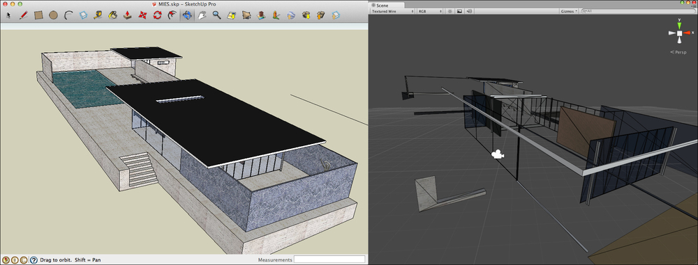
Upon closer inspection, the geometry is actually available in the model, but can only be seen from the other side, for example, from the bottom. CAD software often displays front and back-faces of geometry, whereas Unity hides back-faces for performance reasons (namely, back-face culling). The order in which vertices of faces are connected defines the face orientation. If you don't pay attention to face orientation during modeling, gaps will appear inside Unity. This problem is not unique to Unity. Abvent Artlantis, a rendering companion software often used by architects, also hides back-faces. We have encountered this numerous times when students are trying to import SketchUp models. This is less problematic when you model with volumes or primitive objects, as they are usually well oriented to start with.
The solution is to either display both sides of the geometry, which effectively doubles the geometry to show on screen, or to flip the wrongly oriented faces in the modeling system, which is obviously recommended. In a correct model, only front faces should be visible. In the case of SketchUp, front and back-faces are both visible, but they have different materials applied, which complicates conversion to Unity.
When you model with single faces, this really becomes problematic. The face will only be visible from the front side and is missing completely when looking from the back. If you are modeling fences or other thin elements, such as glass panes, you need to either model them as thin boxes or export the model with faces for both sides separately. If supported, turn off back-face display in the CAD system, to better assess how the model will appear inside Unity. When using SketchUp, switch to the Monochrome Face Style, which will show all face orientation mistakes (back-faces) in a light blue color, as shown in the following screenshot:
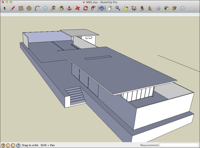
Right click on the problematic faces and choose the Reverse Faces… option. Before you export any SketchUp model to Unity, switch to this face style and flip all blue faces. Beware that you might need to re-assign materials, as the front face material will be moved to the other side as well, which is not visible in the Monochrome face style.
Texture coordinates are the link between a texture image (for example, a picture of a brick wall) and the geometry onto which it is applied. Texture coordinates are stored inside the vertices of geometry, alongside geometric coordinates.
While most game modelers colorize geometry using textures, many architectural models contain plain and solid colors. When exporting to Unity, this becomes a problem, as faces will not have their texture coordinates properly set up. When you assign a material inside Unity or change the Base (RGB) texture, it will not be positioned correctly. Chances are that you'll only see a single color, usually the border pixel(s) of the texture or that the position and scale of the texture map on the geometry is inconsistent. The following image displays a basic brick texture and how it is mapped on the imported geometry. The stretched pixels indicate an incorrect mapping setup.
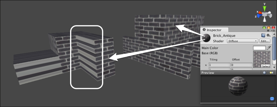
To alter these coordinates from within Unity, Unity requires separate tools and is really cumbersome, certainly when the original model changes. Always assign textures in the original model, even if the texture itself is only a placeholder.
The way models are created for game environments is fundamentally different from the way architectural models are set up. Professional game modelers are trained to use as little geometry as possible. Even though Unity is capable of displaying fairly large and complex models, performance will suffer, so every possible face that is never seen is omitted.
In a CAD model, this is not the case. A door that is placed inside a wall will cover the side of the wall opening, but the faces of this side are still modeled, even if they are never seen. Likewise, cabinets and closets are commonly placed against a wall. If the cabinet never moves, game modelers would remove those faces, whereas architects need them to be visible, as the model can be displayed with or without the covering objects visible.
This problem is harder to solve, as the architectural model has many different purposes. In any case, the architect would need to set up a specific model display to be used when exporting for real-time usage. Such a view needs to hide as much geometry as possible and hide at least those elements that are never to be seen in the real-time model.
It can be valuable to export the CAD or BIM model in chunks, providing more flexibility inside Unity to selectively show or hide parts of the model. Depending on the use case, you could toggle furniture, technical installations, outside walls or even different design alternatives. The next section will show this with the help of an example.
Most CAD systems support a notion of a Block or a Symbol. These are objects that occur repeatedly, with identical properties. Typical examples include furniture or sanitary equipment. This technique is called instancing , in general. Such objects are used to diminish file sizes and optimize modeling and display performance. Instancing in Unity is organized using Prefabs, which are displayed with a blue name in the editor.
However, when converting CAD models to Unity, instancing information often gets lost, depending on the way the export function was implemented. This is something to be tested early on, since it can make a huge difference in performance.
If the export process does not support instancing, it might be beneficial to export only the unique geometry and assemble the model inside Unity, after turning each unique element into a single prefab. For example, in a restaurant project, export a single table into a separate file and load that into your Unity project as a prefab alongside the building geometry. When copying this, all instances will be identical and the system can optimize its performance automatically. This is more efficient than exporting the full scene with all tables included. Beware that this can be a considerable effort, so do this only if required, for example, when the player is able to move or interact with the tables.