

We will now put the GLSLShader class to use by implementing an application to render a simple colored triangle on screen.
For this recipe, we assume that the reader has created a new empty Win32 project with OpenGL 3.3 core profile as shown in the first recipe. The code for this recipe is in the Chapter1/SimpleTriangle directory.
Tip
In all of the code samples in this book, you will see a macro GL_CHECK_ERRORS dispersed throughout. This macro checks the current error bit for any error which might be raised by passing invalid arguments to an OpenGL function, or when there is some problem with the OpenGL state machine. For any such error, this macro traps it and generates a debug assertion signifying that the OpenGL state machine has some error. In normal cases, no assertion should be raised, so adding this macro helps to identify errors. Since this macro calls glGetError inside a debug assert, it is stripped in the release build.
Now we will look at the different transformation stages through which a vertex goes, before it is finally rendered on screen. Initially, the vertex position is specified in what is called the object space. This space is the one in which the vertex location is specified for an object. We apply modeling transformation to the object space vertex position by multiplying it with an affine matrix (for example, a matrix for scaling, rotating, translating, and so on). This brings the object space vertex position into world space. Next, the world space positions are multiplied by the camera/viewing matrix which brings the position into view/eye/camera space. OpenGL stores the modeling and viewing transformations in a single (modelview) matrix.
The view space positions are then projected by using a projection transformation which brings the position into clip space. The clip space positions are then normalized to get the normalized device coordinates which have a canonical viewing volume (coordinates are [-1,-1,0] to [1,1,1] in x, y, and z coordinates respectively). Finally, the viewport transformation is applied which brings the vertex into window/screen space.
Let us start this recipe using the following steps:
Define a vertex shader (
shaders/shader.vert) to transform the object space vertex position to clip space.#version 330 core layout(location = 0) in vec3 vVertex; layout(location = 1) in vec3 vColor; smooth out vec4 vSmoothColor; uniform mat4 MVP; void main() { vSmoothColor = vec4(vColor,1); gl_Position = MVP*vec4(vVertex,1); }Define a fragment shader (
shaders/shader.frag) to output a smoothly interpolated color from the vertex shader to the frame buffer.#version 330 core smooth in vec4 vSmoothColor; layout(location=0) out vec4 vFragColor; void main() { vFragColor = vSmoothColor; }Load the two shaders using the
GLSLShaderclass in theOnInit()function.shader.LoadFromFile(GL_VERTEX_SHADER, "shaders/shader.vert"); shader.LoadFromFile(GL_FRAGMENT_SHADER,"shaders/shader.frag"); shader.CreateAndLinkProgram(); shader.Use(); shader.AddAttribute("vVertex"); shader.AddAttribute("vColor"); shader.AddUniform("MVP"); shader.UnUse();Create the geometry and topology. We will store the attributes together in an interleaved vertex format, that is, we will store the vertex attributes in a struct containing two attributes, position and color.
vertices[0].color=glm::vec3(1,0,0); vertices[1].color=glm::vec3(0,1,0); vertices[2].color=glm::vec3(0,0,1); vertices[0].position=glm::vec3(-1,-1,0); vertices[1].position=glm::vec3(0,1,0); vertices[2].position=glm::vec3(1,-1,0); indices[0] = 0; indices[1] = 1; indices[2] = 2;
Store the geometry and topology in the buffer object(s). The stride parameter controls the number of bytes to jump to reach the next element of the same attribute. For the interleaved format, it is typically the size of our vertex struct in bytes, that is,
sizeof(Vertex).glGenVertexArrays(1, &vaoID); glGenBuffers(1, &vboVerticesID); glGenBuffers(1, &vboIndicesID); glBindVertexArray(vaoID); glBindBuffer (GL_ARRAY_BUFFER, vboVerticesID); glBufferData (GL_ARRAY_BUFFER, sizeof(vertices), &vertices[0], GL_STATIC_DRAW); glEnableVertexAttribArray(shader["vVertex"]); glVertexAttribPointer(shader["vVertex"], 3, GL_FLOAT, GL_FALSE,stride,0); glEnableVertexAttribArray(shader["vColor"]); glVertexAttribPointer(shader["vColor"], 3, GL_FLOAT, GL_FALSE,stride, (const GLvoid*)offsetof(Vertex, color)); glBindBuffer(GL_ELEMENT_ARRAY_BUFFER, vboIndicesID); glBufferData(GL_ELEMENT_ARRAY_BUFFER, sizeof(indices), &indices[0], GL_STATIC_DRAW);
Set up the resize handler to set up the viewport and projection matrix.
void OnResize(int w, int h) { glViewport (0, 0, (GLsizei) w, (GLsizei) h); P = glm::ortho(-1,1,-1,1); }Set up the rendering code to bind the
GLSLShadershader, pass the uniforms, and then draw the geometry.void OnRender() { glClear(GL_COLOR_BUFFER_BIT|GL_DEPTH_BUFFER_BIT); shader.Use(); glUniformMatrix4fv(shader("MVP"), 1, GL_FALSE, glm::value_ptr(P*MV)); glDrawElements(GL_TRIANGLES, 3, GL_UNSIGNED_SHORT, 0); shader.UnUse(); glutSwapBuffers(); }Delete the shader and other OpenGL objects.
void OnShutdown() { shader.DeleteShaderProgram(); glDeleteBuffers(1, &vboVerticesID); glDeleteBuffers(1, &vboIndicesID); glDeleteVertexArrays(1, &vaoID); }
For this simple example, we will only use a vertex shader (shaders/shader.vert) and a fragment shader (shaders/shader.frag). The first line in the shader signifies the GLSL version of the shader. Starting from OpenGL v3.0, the version specifiers correspond to the OpenGL version used. So for OpenGL v3.3, the GLSL version is 330. In addition, since we are interested in the core profile, we add another keyword following the version number to signify that we have a core profile shader.
Another important thing to note is the layout qualifier. This is used to bind a specific integral attribute index to a given per-vertex attribute. While we can give the attribute locations in any order, for all of the recipes in this book the attribute locations are specified starting from 0 for position, 1 for normals, 2 for texture coordinates, and so on. The layout location qualifier makes the glBindAttribLocation call redundant as the location index specified in the shader overrides any glBindAttribLocation call.
The vertex shader simply outputs the input per-vertex color to the output (vSmoothColor). Such attributes that are interpolated across shader stages are called varying attributes. It also calculates the clip space position by multiplying the per-vertex position (vVertex) with the combined modelview projection (MVP) matrix.
vSmoothColor = vec4(vColor,1); gl_Position = MVP*vec4(vVertex,1);
Tip
By prefixing smooth to the output attribute, we tell the GLSL shader to do smooth perspective-correct interpolation for the attribute to the next stage of the pipeline. The other qualifiers usable are flat and noperspective. When no qualifier is specified the default interpolation qualifier is smooth.
The fragment shader writes the input color (vSmoothColor) to the frame buffer output (vFragColor).
vFragColor = vSmoothColor;
In the simple triangle demo application code, we store the GLSLShader object reference in the global scope so that we can access it in any function we desire. We modify the OnInit() function by adding the following lines:
shader.LoadFromFile(GL_VERTEX_SHADER, "shaders/shader.vert");
shader.LoadFromFile(GL_FRAGMENT_SHADER,"shaders/shader.frag");
shader.CreateAndLinkProgram();
shader.Use();
   shader.AddAttribute("vVertex");
    shader.AddAttribute("vColor");
    shader.AddUniform("MVP");
shader.UnUse();The first two lines create the GLSL shader of the given type by reading the contents of the file with the given filename. In all of the recipes in this book, the vertex shader files are stored with a .vert extension, the geometry shader files with a .geom extension, and the fragment shader files with a .frag extension. Next, the GLSLShader::CreateAndLinkProgram function is called to create the shader program from the shader object. Next, the program is bound and then the locations of attributes and uniforms are stored.
We pass two attributes per-vertex, that is vertex position and vertex color. In order to facilitate the data transfer to the GPU, we create a simple Vertex struct as follows:
struct Vertex {
glm::vec3 position;
glm::vec3 color;
};
Vertex vertices[3];
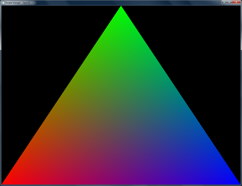
GLushort indices[3];Next, we create an array of three vertices in the global scope. In addition, we store the triangle's vertex indices in the indices global array. Later we initialize these two arrays in the OnInit() function. The first vertex is assigned the red color, the second vertex is assigned the green color, and the third vertex is assigned the blue color.
vertices[0].color=glm::vec3(1,0,0);
vertices[1].color=glm::vec3(0,1,0);
vertices[2].color=glm::vec3(0,0,1);

vertices[0].position=glm::vec3(-1,-1,0);
vertices[1].position=glm::vec3(0,1,0);
vertices[2].position=glm::vec3(1,-1,0);

indices[0] = 0;
indices[1] = 1;
indices[2] = 2;
Next, the vertex positions are given. The first vertex is assigned an object space position of (-1,-1, 0), the second vertex is assigned (0,1,0), and the third vertex is assigned (1,-1,0). For this simple demo, we use an orthographic projection for a view volume of (-1,1,-1,1). Finally, the three indices are given in a linear order.
In OpenGL v3.3 and above, we typically store the geometry information in buffer objects, which is a linear array of memory managed by the GPU. In order to facilitate the handling of buffer object(s) during rendering, we use a vertex array object (VAO). This object stores references to buffer objects that are bound after the VAO is bound. The advantage we get from using a VAO is that after the VAO is bound, we do not have to bind the buffer object(s).
In this demo, we declare three variables in global scope; vaoID for VAO handling, and vboVerticesID and vboIndicesID for buffer object handling. The VAO object is created by calling the glGenVertexArrays function. The buffer objects are generated using the glGenBuffers function. The first parameter for both of these functions is the total number of objects required, and the second parameter is the reference to where the object handle is stored. These functions are called in the OnInit() function.
glGenVertexArrays(1, &vaoID); glGenBuffers(1, &vboVerticesID); glGenBuffers(1, &vboIndicesID); glBindVertexArray(vaoID);
After the VAO object is generated, we bind it to the current OpenGL context so that all successive calls affect the attached VAO object. After the VAO binding, we bind the buffer object storing vertices (vboVerticesID) using the glBindBuffer function to the GL_ARRAY_BUFFER binding. Next, we pass the data to the buffer object by using the glBufferData function. This function also needs the binding point, which is again GL_ARRAY_BUFFER. The second parameter is the size of the vertex array we will push to the GPU memory. The third parameter is the pointer to the start of the CPU memory. We pass the address of the vertices global array. The last parameter is the usage hint which tells the GPU that we are not going to modify the data often.
glBindBuffer (GL_ARRAY_BUFFER, vboVerticesID); glBufferData (GL_ARRAY_BUFFER, sizeof(vertices), &vertices[0], GL_STATIC_DRAW);
The usage hints have two parts; the first part tells how frequently the data in the buffer object is modified. These can be STATIC (modified once only), DYNAMIC (modified occasionally), or STREAM (modified at every use). The second part is the way this data will be used. The possible values are DRAW (the data will be written but not read), READ (the data will be read only), and COPY (the data will be neither read nor written). Based on the two hints a qualifier is generated. For example, GL_STATIC_DRAW if the data will never be modified and GL_DYNAMIC_DRAW if the data will be modified occasionally. These hints allow the GPU and the driver to optimize the read/write access to this memory.
In the next few calls, we enable the vertex attributes. This function needs the location of the attribute, which we obtain by the GLSLShader::operator[], passing it the name of the attribute whose location we require. We then call glVertexAttributePointer to tell the GPU how many elements there are and what is their type, whether the attribute is normalized, the stride (which means the total number of bytes to skip to reach the next element; for our case since the attributes are stored in a Vertex struct, the next element's stride is the size of our Vertex struct), and finally, the pointer to the attribute in the given array. The last parameter requires explanation in case we have interleaved attributes (as we have). The offsetof operator returns the offset in bytes, to the attribute in the given struct. Hence, the GPU knows how many bytes it needs to skip in order to access the next attribute of the given type. For the vVertex attribute, the last parameter is 0 since the next element is accessed immediately after the stride. For the second attribute vColor, it needs to hop 12 bytes before the next vColor attribute is obtained from the given vertices array.
glEnableVertexAttribArray(shader["vVertex"]); glVertexAttribPointer(shader["vVertex"], 3, GL_FLOAT, GL_FALSE,stride,0); glEnableVertexAttribArray(shader["vColor"]); glVertexAttribPointer(shader["vColor"], 3, GL_FLOAT, GL_FALSE,stride, (const GLvoid*)offsetof(Vertex, color));
The indices are pushed similarly using glBindBuffer and glBufferData but to a different binding point, that is, GL_ELEMENT_ARRAY_BUFFER. Apart from this change, the rest of the parameters are exactly the same as for the vertices data. The only difference being the buffer object, which for this case is vboIndicesID. In addition, the passed array to the glBufferData function is the indices array.
glBindBuffer(GL_ELEMENT_ARRAY_BUFFER, vboIndicesID); glBufferData(GL_ELEMENT_ARRAY_BUFFER, sizeof(indices), &indices[0], GL_STATIC_DRAW);
To complement the object generation in the OnInit() function, we must provide the object deletion code. This is handled in the OnShutdown() function. We first delete the shader program by calling the GLSLShader::DeleteShaderProgram function. Next, we delete the two buffer objects (vboVerticesID and vboIndicesID) and finally we delete the vertex array object (vaoID).
void OnShutdown() {
shader.DeleteShaderProgram();
glDeleteBuffers(1, &vboVerticesID);
glDeleteBuffers(1, &vboIndicesID);
glDeleteVertexArrays(1, &vaoID);
}Tip
We do a deletion of the shader program because our GLSLShader object is allocated globally and the destructor of this object will be called after the main function exits. Therefore, if we do not delete the object in this function, the shader program will not be deleted and we will have a graphics memory leak.
The rendering code of the simple triangle demo is as follows:
void OnRender() {
    glClear(GL_COLOR_BUFFER_BIT|GL_DEPTH_BUFFER_BIT);
    shader.Use();
    glUniformMatrix4fv(shader("MVP"), 1, GL_FALSE, glm::value_ptr(P*MV));
    glDrawElements(GL_TRIANGLES, 3, GL_UNSIGNED_SHORT, 0);
    shader.UnUse();
    glutSwapBuffers();
}The rendering code first clears the color and depth buffer and binds the shader program by calling the GLSLShader::Use() function. It then passes the combined modelview and projection matrix to the GPU by invoking the glUniformMatrix4fv function. The first parameter is the location of the uniform which we obtain from the GLSLShader::operator() function, by passing it the name of the uniform whose location we need. The second parameter is the total number of matrices we wish to pass. The third parameter is a Boolean signifying if the matrix needs to be transposed, and the final parameter is the float pointer to the matrix object. Here we use the glm::value_ptr function to get the float pointer from the matrix object. Note that the OpenGL matrices are concatenated right to left since it follows a right handed coordinate system in a column major layout. Hence we keep the projection matrix on the left and the modelview matrix on the right. For this simple example, the modelview matrix (MV) is set as the identity matrix.
After this function, the glDrawElements call is made. Since we have left our VAO object (vaoID) bound, we pass 0 to the final parameter of this function. This tells the GPU to use the references of the GL_ELEMENT_ARRAY_BUFFER and GL_ARRAY_BUFFER binding points of the bound VAO. Thus we do not need to explicitly bind the vboVerticesID and vboIndicesID buffer objects again. After this call, we unbind the shader program by calling the GLSLShader::UnUse() function. Finally, we call the glutSwapBuffer function to show the back buffer on screen. After compiling and running, we get the output as shown in the following figure:
Learn modern 3D graphics programming by Jason L. McKesson at http://www.arcsynthesis.org/gltut/Basics/Basics.html.