

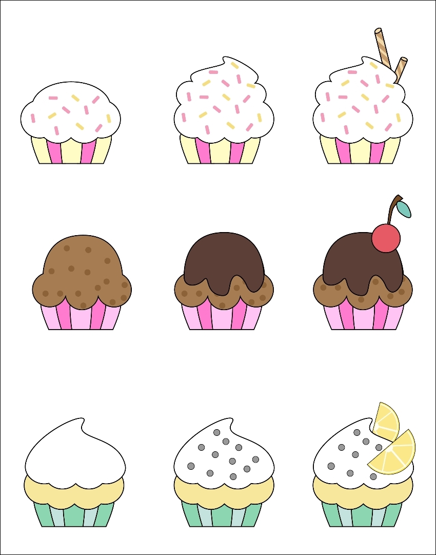
The fundamental bricks of a 2D game in Unity are the Sprites. You can think of them as pictures, but actually as we are going to see, they are something more. In fact, one image can contain more than one Sprite. Usually, this kind of image takes the name of a Sprite Sheet. Here is an example of a Sprite Sheet within our package:
There are different reasons why we want to have all the Sprites on a single image, rather than display them separately. The most important one is efficiency. Every time you want to render something on the screen, this has to be rendered by the graphics card in your computer. If all the Sprites are in separate images, the graphics card will have to process a lot of images. As a result, your game will run slowly.
Another reason for having Sprite Sheets is for animations. While 3D animations are made of data that describes how a 3D model has to be moved, 2D animations are made of frames. Like a movie or a cartoon, an animation is made of different images, or in this case, Sprites. Each of them describes a moment, and if you change them quickly enough, such as 25 per second, you can give the illusion of movement. Having all of the frames in a unique image is both efficient and well organized.
Naturally, there are other reasons for Sprite Sheets, but the two preceding reasons should be enough to convince you that Sprite Sheets are the best practice. On the other hand, there is a tradeoff to pay: the game engine needs to be able to distinguish between them on the image. We will see how Unity handles this in the following sections. But before we move on, there are other important concepts to learn about Sprites in Unity.
Like a 3D object, a Sprite also has a pivot point. Usually, this is located in the middle, but it can be changed in the Sprite Editor. The pivot point is where Unity starts to do all the calculations from. For instance, when you give a position for the Sprite to be within the Scene, Unity places the pivot point in that specific location, and then draws the Sprite around it. The pivot point is also important for rotations. Every time we rotate the Sprite, the rotation will be around the pivot point. In other words, during a rotation, the pivot point is the only point that does not change position.
This can be better explained with a screenshot, where the arrow is indicating the location of the pivot point:

As you can see, there is the same Sprite rotated by 90 degrees clockwise. The one on the left has the pivot point in the middle, whereas the one on the right has it toward the left-hand side (the pivot point can be identified by the blue circle). Of course, you can make them coincide with a translation, but it is important to keep where it is in mind, especially when we code, in order to easily achieve what we want.
Now, there is another aspect to take into account about Sprites. In a 2D game, both the background and the character who is moving around the world are considered Sprites. However, we would like to render the background behind the character, and not vice versa. Therefore, the Sprites are rendered in a certain order that determines which one should render on top of the others.
In Unity there are two main ways to decide this order:
Sorting Layers: Each Sprite Render, which is a component attached to a game object that renders the Sprite selected, has a variable called Sorting Layer. There, we can chose on which layer the Sprite will be rendered. The order of the different sorting layers can be determined in the Tags and Layers Settings (we will see how to access this menu later on in the chapter). Furthermore, Sorting Layers can offer an internal order for Sprites within the same layer by using the Order In Layer variable, which is always in the Sprite Render component.
Z-Buffering: Since a 2D object only needs two coordinates to describe its position (the x and y axes), we have the z axis to describe depth. Unity uses depth to determine which Sprite should be rendered first. Since you need to imagine this as a depth, it's good practice to use only negative values. The greater the negative value, the closer the character or object is to the camera.
There aren't any great differences between these methods in terms of computational efficiency. Therefore, both can be used. Actually, they can also be used together. A general approach is to use the z axis for visually structuring characters. Imagine a character who is carrying a weapon. Depending on which hand the weapon is held in and in which direction the character is facing, the weapon should be rendered behind the character or in front of it. Sorting Layers, instead, are used for organizing the Sprites at a higher level, such as background, foreground, player, enemies, and so on.
However, for the sake of learning, in this book we will not use Sorting Layers, but only Z-Buffering, since it can be easily changed within the code.
Before we mention this component, it might be worth discussing it a bit more.
This component will be automatically attached every time we add a Sprite to the scene. It should look like the following screenshot:
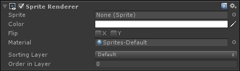
Let's break down the different parameters:
Sprite: This holds the Sprite that it has to render.
Color: This is a color that is multiplied to the Sprite image. If you know bit about shaders and renderers, this is actual the vertex color of the rendered mesh.
Flip: This defines on which axis the Sprite needs to be flipped. This is a new function from Unity 5.3.
Material: This is the material Unity should use to render the Sprite. The default one is more than enough for our needs. If you are an expert in shaders, there are two kinds of built-in shader. Both are simple alpha-blended shaders, but the Diffuse one interacts with light, generating a (
0,0,-1) front-facing normal vector.Sorting Layer: This is in which Sorting Layer the Sprite should be rendered (as discussed previously).
Order in Layer: This is the order within that particular Sorting Layer (as we discussed previously).
If you have downloaded and imported the package from the Getting ready section, we should now have all the files inside our Project folder. If you go to the Graphics/towers folder and select cupcake_tower_sheet-01, we should see the following in the Inspector:
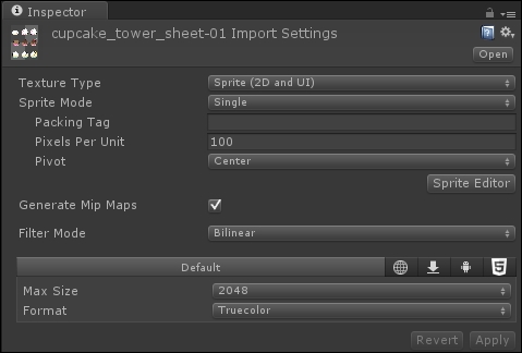
These are the Import Settings, where different options can be set. After we have changed something, we need to press the Apply button at the bottom to confirm the changes. Likewise, if we are not happy, we can press the Revert button to discard our changes.
It is important to note that the Texture Type is Sprite (2D and UI). In 2D mode, Unity always imports image files as Sprites and not as Textures.
The other important parameter that we need to take into consideration is the Sprite Mode. By default, it is set to Single, but it can be changed to Multiple or Polygonal (only from Unity 5.3). As the names suggests, the first is used when the image contains a single Sprite, and the second mode is used when we have a Sprite Sheet with more than one Sprite. The last one is used to identify a polygonal Sprite with a custom number of edges.
Furthermore, the Pixel Per Unit parameter determines how big the Sprite will be in the Scene. It represents how many pixels are needed to have a unitary length in the Scene View. By default, it is set to 100, but you should modify this value when you need to adapt your assets and change them to the right dimensions. However, if you already have a scale in mind, creating the graphics accordingly could be a useful time saver for the later stages of development.
With regard to the other settings (Packing Tag, Generate Mip Maps, Filter Mode, Max Size, and Format), we will see them in detail in the last chapter of this book, when we will talk about optimization.
Since the file that we have selected contains more than one Sprite, let's set the Sprite Mode to Multiple before we move on to the next section.
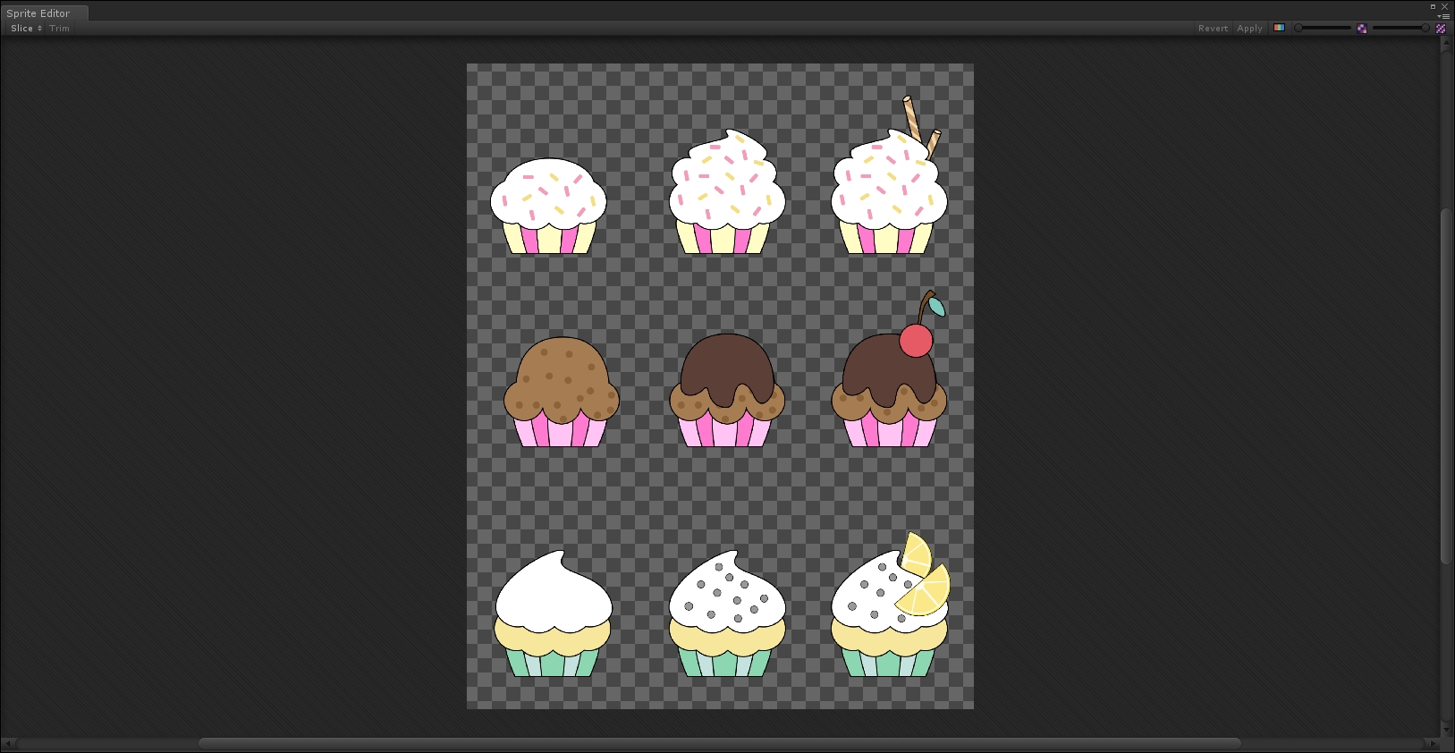
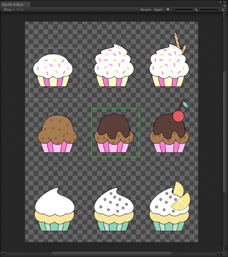
In Import Settings, there is also a button named Sprite Editor. If we press this button, a new window appears. This is the Sprite Editor, as we can see in the following screenshot:
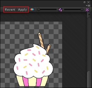
If we mess things up, we can always revert them back by clicking on the Revert button in the top-right corner of the Sprite Editor. Next to it, you can also find an Apply button, which you use to confirm your choices, so be careful which one you press!
For your own reference, they are highlighted in the next screenshot:
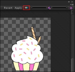
Near these two buttons, you can find some features that might help you when working in the Sprite Editor. The first is a button that is easy to miss, but that allows you to switch from the colored asset (RGB channels) to B/W (alpha channel). This is particularly useful when you need to define contours and the image has transparency, as we will see later. So that you avoid missing it, you can find it highlighted in the following screenshot:
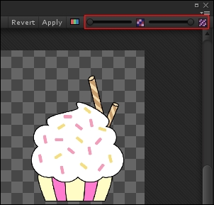
To the right of it, there are two sliders, which allow you to either zoom in/out or increase/decrease the resolution (number of pixels). These features are shown in the following screenshot:
The Sprite Editor allows you to do different things. For single sprites, it gives the possibility to change the pivot point. For Sprite Sheets, such as in this case, it is the way for Unity to understand how many Sprites there are and where they are located on the image.
Now, there are different ways to do this, so let's have a look at them in more detail.
In manual mode, it's you that selects each Sprite in the image, and tells Unity where it is and how big it is.
To create a new selection, you need to click in a corner of your Sprite and drag the mouse until you have selected the whole Sprite. A green rectangle appears, showing you the selected area, and you can see how the Sprite changes in real time while dragging the mouse. If you release the mouse button, the green rectangle becomes blue and Unity will interpret everything that is inside it as a Sprite.
You can create as many selections (rectangles) as you want. Also, by clicking on them, you can move them around the image and change their dimensions. Here is an example of our Sprite Sheet with some manual selections:
If you have made a rectangle that is bigger than the Sprite, Unity can try to trim it. In the top-left corner of the Sprite Editor, there is the Trim button, as shown in the following screenshot:
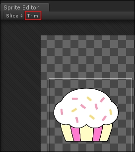
It is active only when a selection is highlighted. If you don't like the final result, you can always modify the selection.
Furthermore, in the middle of each selection, there is a small blue circle. This is the Pivot Point of that selection. We are free to drag it to another position. However, other than very specific cases, having the pivot point in the middle is common and useful. So at the moment, don't worry much about it, and just leave it in the middle.
Another thing you may notice is four small green squares in the middle of each edge of the rectangle. We will need them to do 9-slice scaling in a few sections.
Once we have highlighted a selection, it is possible to modify it in more detail by using the menu that appears in the bottom-right corner of the Sprite Editor. Here is what it looks like:
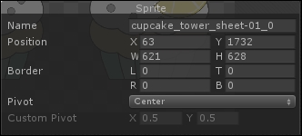
From this menu, you can modify the name of the selection, which will be reflected in the name of the Sprite when we use it. By typing numeric values, you can precisely set the dimension, the position, and the Pivot Point of the selection.
To conclude, manual mode is particularly useful when the shape and the dimensions of the Sprite in the Sprite Sheet are different. Even if the designer of the picture is careful and avoids placing single Sprites close to each other, the objects can still have very different dimensions.
In automatic mode, Unity tries to slice the Sprites, which means it creates the different selections for you. However, to get a better result, you need to give some information about the image. In any case, once Unity has offered its selections for the image, you can still modify them as you would in manual mode.
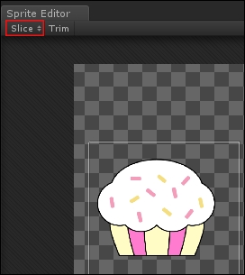
In the top-left corner of the Sprite Editor, next to the Trim button, we can see the Slice button, as shown here:
By clicking on it, a menu appears that looks like this:
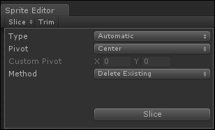
As you can see, we can select different types. Let's go through them.
The Automatic type is the best guess of Unity about the selections. Besides the method that we will see in a bit, and where to place the pivot points of the selections, there is nothing else to set. Unity will do everything automatically, and if we don't need our Sprites to be the same size, this way works pretty well. Here is the final result applied to our image:

The Automatic type comes with three different methods:
The Delete Existing method erases all the previous selections before slicing the image
The Smart method tries to create selections for the Sprites that are not yet in a selection
The Safe method creates new selections without erasing the previous ones
The Grid By Cell Size type, instead, divides the image into a grid of selections. From the menu, you can select the dimension of each cell. As a result, the number of cells will depend on how big they are.
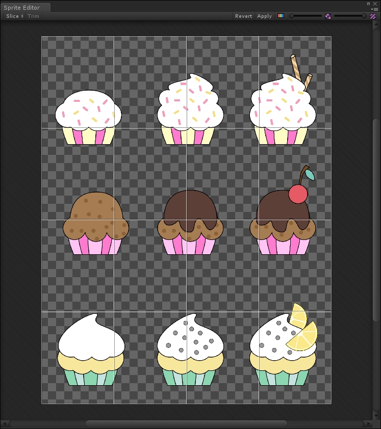
The Grid By Cell Count type, again, divides the image into a grid of selections. However, this time, you can set from the menu how many cells will be in the image, and their dimensions will depend on this. Here is our image sliced using a 4 x 4 grid:
From Unity 5.3, you can have access to this new feature of the Sprite Editor. In order to use it, you need to set the Sprite Mode to Polygonal in the import setting of the asset.
In this mode, Unity automatically slices the Sprite as a polygon. Once we open the Sprite Editor, we will immediately be able to set the number of sides or edges of the polygon. If we miss this, we can always press the Change Shape button in the top-left corner of the Sprite Editor, as shown here:
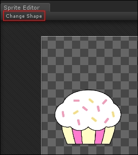
If we select an octagon (eight-sided polygon), this is the final result we would get in our image:

There is another important feature of the Sprite Editor, called 9-slice. It is used when a UI element needs different scaling in different parts of it. This feature is in the Sprite Editor because UI elements are treated as Sprites by Unity.
We will see the UI in another chapter, but let's start understanding why some UI elements need to be scaled differently. As you know, the game can run on different screens that usually have different resolutions and aspect ratios. As a result, the UI needs to be scaled properly depending on the screen. However, if you create a button with beautiful rounded corners, once it's scaled they will look completely different to how we had originally designed them, and not for the better.
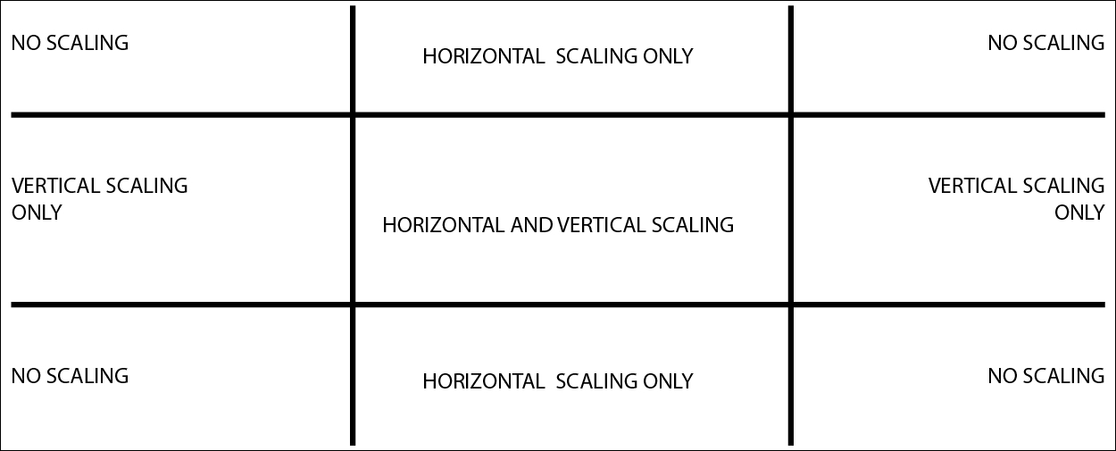
The 9-slice technique avoids this problem by defining nine sections on the Sprite that will be scaled differently. In particular, corners will not be scaled at all: only edges along their axis and the central section will scale in all the directions. The following image should help in understanding these nine sections and how they scale:
Let's take a UI image to learn how to do a 9-slice with the Sprite Editor of Unity. Select ui_blank_square_icon_pink in the Graphics/UI folder, and open it in the Sprite Editor. Since we didn't set its Sprite Mode to Multiple, we have only one selection around the entire image.
As we have already noticed, there are some green squares at the edges of our selection. If we drag them, we can divide the image into nine sections, and we are performing a 9-slice on that Sprite. Here is how the 9-slice should be done with a button:
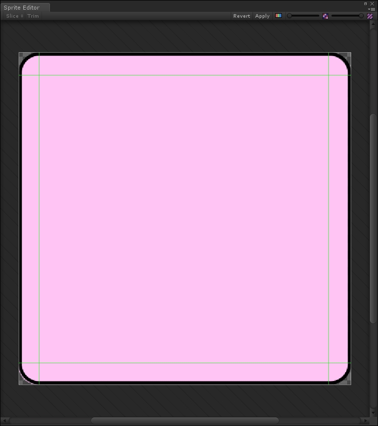
You need to leave the central section as big as possible, and keep the others the right size to include corners and edges.
Now, we should know a lot about the Sprite Editor. I suggest that you practice with the Sprite Editor for a bit before moving to the next section of this book. In fact, you will need to practice the methods that we have covered so far to prepare all our assets for the game we are going to build.
In this section, you will have the chance to practice what we have learned so far. In fact, we need to prepare the assets for our game.
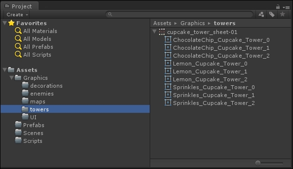
Let's start by selecting Graphics/towers/cupcake_tower_sheet-01 (the same file we used before) and slice it with a 3 x 3 grid. Then, we should rename each Sprite.
In the first row, we can give them these names (from left to right):
Sprinkles_Cupcake_Tower_0Sprinkles_Cupcake_Tower_1Sprinkles_Cupcake_Tower_2
In the second row, we can give them these names:
ChocolateChip_Cupcake_Tower_0ChocolateChip_Cupcake_Tower_1ChocolateChip_Cupcake_Tower_2
Finally, the third row:
Lemon_Cupcake_Tower_0Lemon_Cupcake_Tower_1Lemon_Cupcake_Tower_2
At the end, we should have the following in the Project panel:
Repeat the same process with the Graphics/enemies and Graphics/UI folders by dividing the different Sprite Sheets. Don't forget to assign meaningful names. For the rest of the book, when we refer to an asset, its name will be self-explanatory. For your convenience, the original file where the Sprite has been taken will be specified.