Book Image

Learning AWS Lumberyard Game Development

By : Dr. Edward Lavieri
Book Image

Learning AWS Lumberyard Game Development

By: Dr. Edward Lavieri

Overview of this book

Amazon’s Lumberyard is a 3D cross-platform game development engine for building high-quality AAA games. It makes the process of creating multi-player games and adding realistic characters, stunning terrains, and special effects much faster and more efficient. This book will show you how to use Lumberyard to create a multiplayer 3D game with cloud computing, storage, and Twitch integration for user engagement. We will start with an introduction to Lumberyard and provide an overview of its capabilities and integration options. Once the game engine is installed, we’ll guide you through the creation of an immersive game world with characters. You’ll add animations and audio to bring the game to life. We’ll explore external interactions to support live multiplayer game play, data storage, user engagement, and the back end. By the end of the book, you will be efficient in building cross-platform games using Lumberyard.
Table of Contents (18 chapters)
Learning AWS Lumberyard Game Development
Credits
About the Author
About the Reviewer
www.PacktPub.com
Preface

Understanding the Flow Graph system and UI


Flow Graph is a visual scripting system used to create gameplay in Lumberyard. It is, of course, much more complex than that and is used to create and edit in-game events, AI, game logic, and other aspects of games you create. We'll explore the Flow Graph UI and then review graphs for the game modes detailed in the previous section.

Flow Graph is the system that is used to create flow graphs, are organized in modules. These graphs can be viewed as gameplay blueprints. Graphs comprise of nodes with inputs and outputs. These graphs, or blueprints, determine a game's constraints, rules, and gameplay.

Flow Graph UI

Flow Graph is accessible through the View | Open View Pane | Flow Graph pull-down menu. There are 10 unique interface components. The following screenshot assigns numbers to each component and this is followed by a detailed explanation:

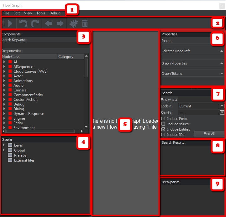
The following table provides component names for each Flow Graph interface area, as depicted in the previous...