

Animating with Math nodes
In this section, we look at how to create interesting animations using Math nodes and other objects in your scene. We will create a basic scaling animation by using the distance value between two objects in our scene and modify the scaling attribute using some easy math. So, let's get started!
For this section, you can start with a new Blender project:
- Delete all of the default objects by pressing A and then pressing X to confirm the deletion.
- Create a plane object by pressing Shift + A and selecting Mesh | Plane.
- Using the pop-up Add Plane dialog box in the lower-left corner of the 3D Viewport window, set the Size setting of the plane to
10 m. Click anywhere in the viewport to confirm these parameters:
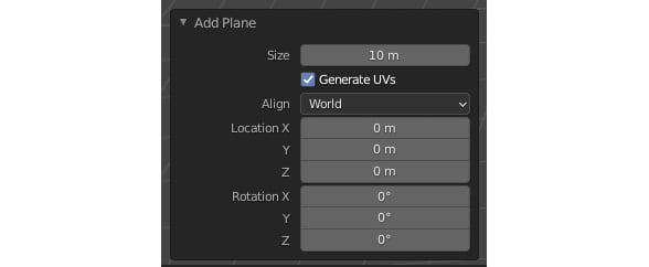
Figure 1.38 – The Add Plane dialog box
- With the plane selected, click on the Geometry Nodes tab at the top of the interface.
- Click on the New button to create a new Geometry Nodes modifier on the plane. You should now see the Geometry Node Editor with two default nodes, Group Input and Group Output.
- Let's create our instance mesh. With your mouse pointer hovering over the 3D Viewport window, press Shift + A and select Mesh | Torus.
- Scale down the torus by 50% by pressing S and then pressing 0.5.
- Move the torus out of view by pressing G then pressing X. Move the mouse until it's away from our plane object.
- Most importantly, we need to apply the scale of this torus; otherwise, we might run into some interesting surprises later. With the torus selected, press Ctrl + A and click on Scale. Now, let's jump back into our node tree!
- Select the plane to enable the Geometry Nodes view. Remember, if you still can't see the nodes, ensure that the Geometry Nodes modifier is highlighted if you have other modifiers in this object.
Now, let's add our first nodes.
- For node number one, we will create a Subdivide node. Slot it in just after the Group Input node.
- Additionally, we need a Point Instance node to instance our mesh. Slot it right before the Group Output node.
- Set your Subdivide node Level to 3.
- Select your new Torus object from the drop-down list of the Point Instance node:
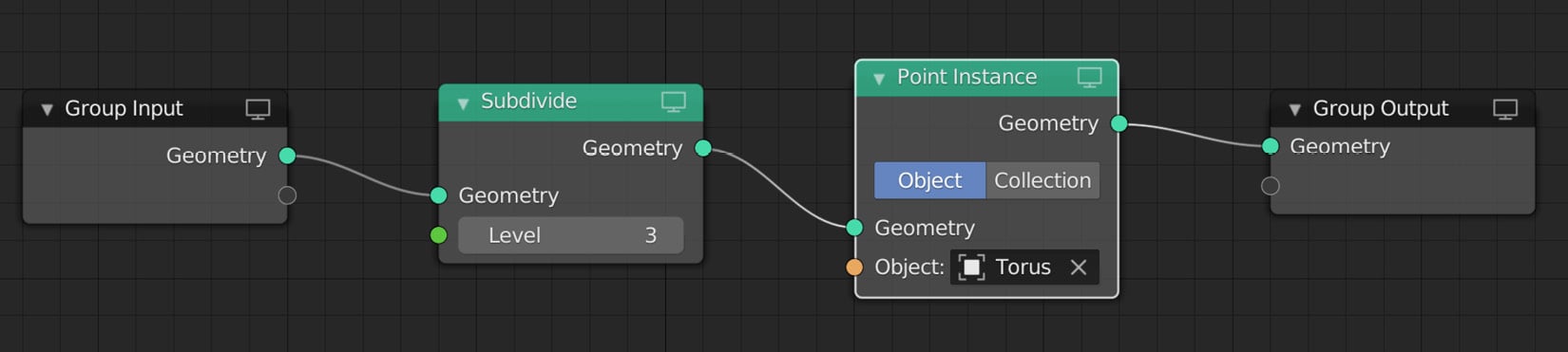
Figure 1.39 – Your node tree should now look like this
Note that you have lots of tori in your scene. Yup, I also didn't know that the plural of a torus is tori until now!
Now, let's create a new cube object in our scene that we will use to calculate some math later on:
- Hover over the 3D Viewport window, press Shift + A, and select Mesh | Cube.
- Move the cube to the edge of our torus instances by pressing G and then pressing X:
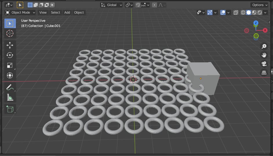
Figure 1.40 – Your scene should now look like this
- Back in our node tree, click on one of the torus instances to view the node tree if it's not visible.
- Add a new node, called the Object Info node, by pressing Shift + A and selecting Input | Object Info or using the search function. We are not going to connect this node to our other nodes at this moment – just place it directly beneath the Subdivide node. We are going to use this node to calculate the distance between our tori and the cube object.
- On this Object Info node, click on the Object drop-down list and select the Cube object from the list. You can also use the eyedropper tool.
- Then, click on the Relative button. This will calculate the current information of the cube and not just the original data:

Figure 1.41 – The Object Info node
Great! You should now have enough instance objects in the scene. In the next section, we will use basic math to calculate the distance between the cube object and each of the instance objects.
The Attribute Vector Math node
Now, let's create our first Math node – the Attribute Vector Math node. There are a few Math nodes available, but for this specific example, we need to use the Attribute Vector Math node because of its Distance operator:
- Press Shift + A and select Attribute | Attribute Vector Math.
- Slot it in right after the Subdivide node:
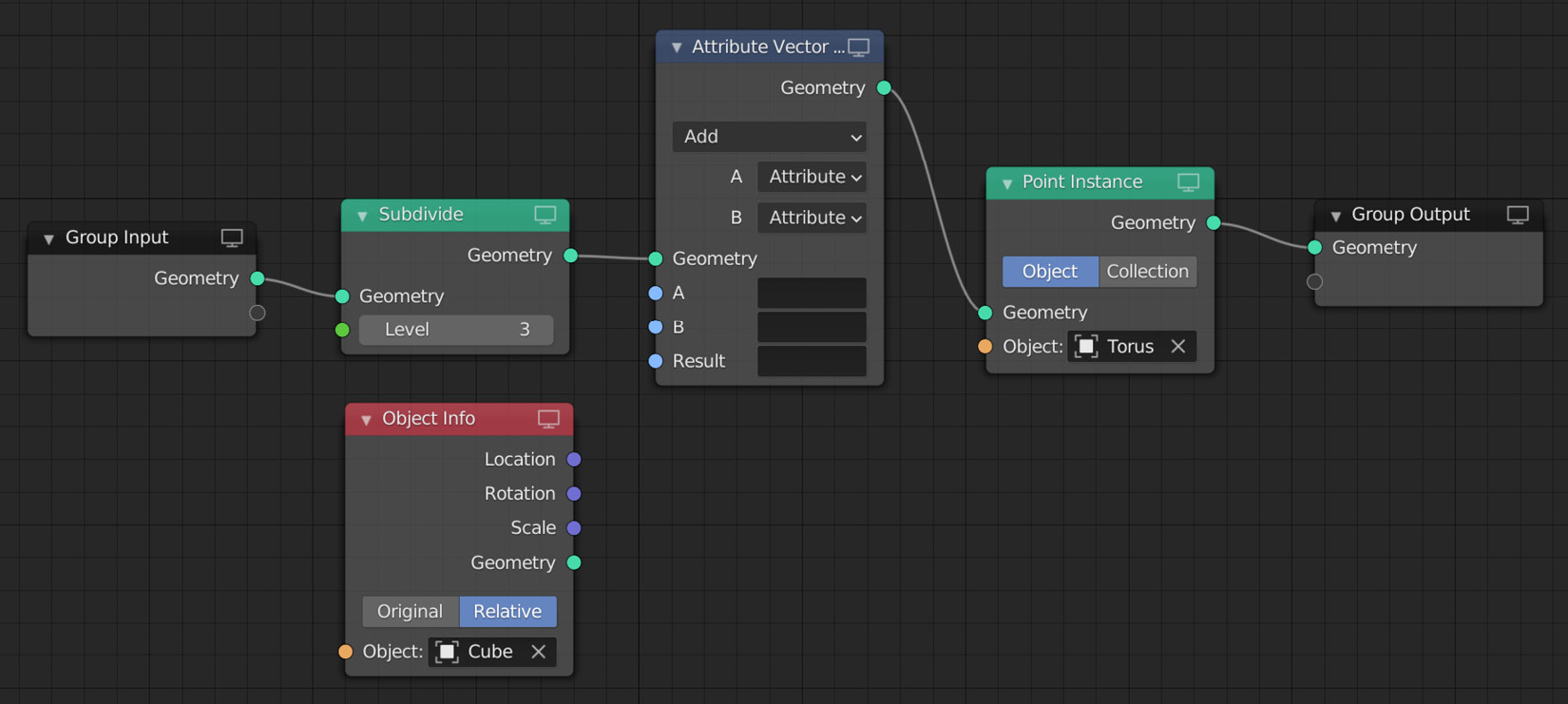
Figure 1.42 – Your node tree should now look like this
Notice that the Object Info node is not yet connected.
Important Note
One thing to bear in mind is that any node that uses an attribute is calculating that attribute for each instance in every frame.
Now, let's take a moment to look at the Attribute Vector Math node and how we will use it. We want to calculate the distance between our Cube object and every Torus instance object. We already have the position value of each Torus instance saved in the position attribute, and with our Object Info node (connected to our cube object), we also have the relative position of the cube. Let's see how we can calculate the distance.
- First, let's change the operation of our Attribute Vector Math node from Add to Distance by clicking on the top drop-down menu on the node and selecting Distance from the many different operations available.
- Then, change B from Attribute to Vector. The reason we're using a vector here is that the cube's position will be a type of vector for each axis:
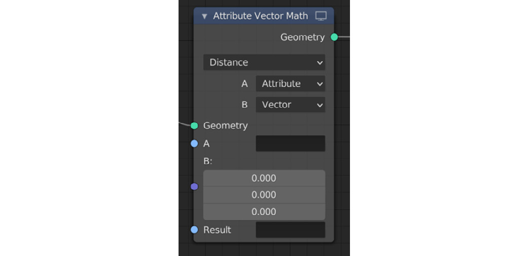
Figure 1.43 – Your node should now look like this
- For attribute A, we want to use our torus positions. To do this, click on the empty box next to A and select position from the list or enter the word
positionand press Enter. - For attribute B, we want to use our cube's position, so let's connect our Object Info node's Location to the Attribute Vector Math node's B input.
Now we need to save the result of this operation to an attribute. Here, we can create our new attribute by entering a new attribute name that's not in use, but an easier option would be to simply overwrite the current scale attribute with our new result. Let's do that next.
- Click on the empty box next to Result and select scale from the list. If you don't see the scale attribute in the list, you can type in the word
scaleand press Enter:
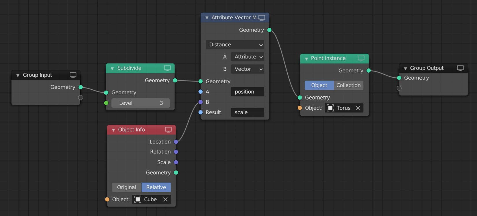
Figure 1.44 – Your node tree should now look like this
- Looking at the 3D Viewport window, you will see that the scale of the instance objects has changed. Instances closer to the cube have a smaller scale, while instances further away from the cube have a bigger scale value. Please refer to the following screenshot:
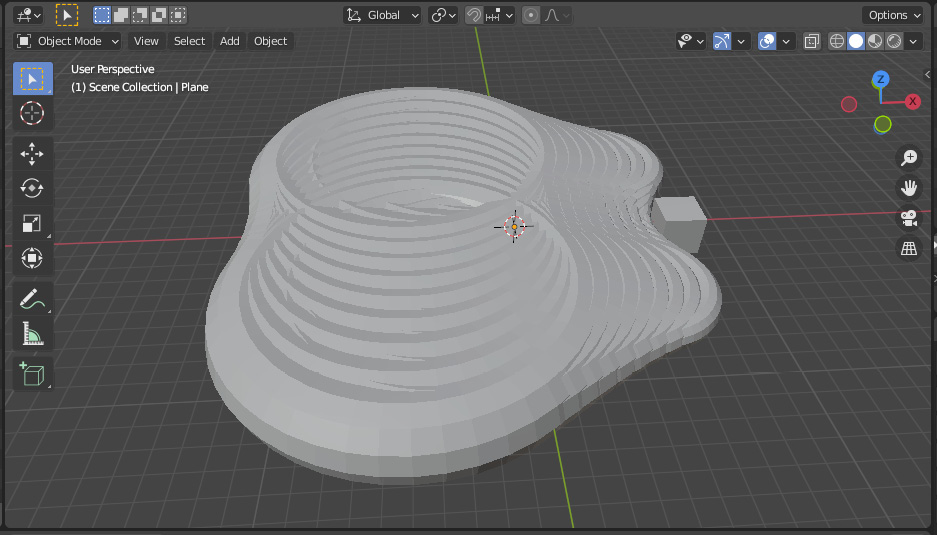
Figure 1.45 – You will see something interesting happening in the 3D Viewport window
As you can see in the 3D Viewport window, our scale factor is currently too big. We can use some more basic math to change that:
- Add a new Attribute Math node and slot it in after the Attribute Vector Math node. Note these are different nodes – one uses vectors and the other uses float data types.
We want to make our scale factor smaller, so let's use the divide operation to do this. We will perform a simple calculation to make our scale factor smaller:
scale / value = smaller scale
- Change the operation at the top of this node from Add to Divide. Leave A as Attribute, but let's change B to Float. This will give us access to change this value manually.
- For Attribute A, select scale from the drop-down menu, or you can enter it manually and press Enter to confirm.
For the Result setting, we can overwrite an existing attribute. In this example, let's overwrite the scale attribute. To do this, click on the empty box next to Result and select scale from the list. Again, you can enter this manually and press Enter to confirm.
Your tori will disappear from the 3D Viewport window because we are now dividing by 0, resulting in their new scale being 0.
- Let's change our B value by clicking and dragging the Float value to the right-hand side – find a number that gives you good results. I chose
10.
Let's examine our node tree:
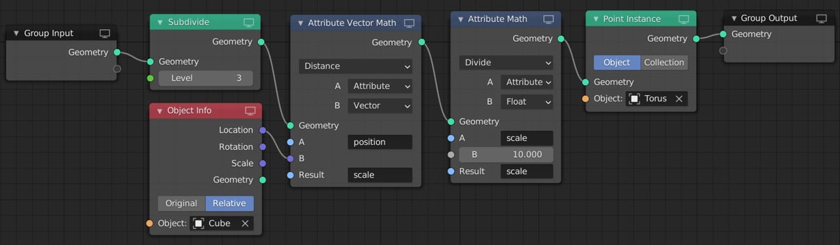
Figure 1.46 – Your node tree should now look like this
First, we are subdividing our plane into three levels. Then, we calculate the distance between our cube object and every torus in our scene by using the Attribute Vector Math node. We then save this distance value into our existing scale attribute, overwriting the current value. Following this, we divide our new scale attribute by 10 (the float we entered manually), resulting in a smaller scale factor.
Now, let's move our cube around the scene to see the effect in action.
- Select your cube in the 3D Viewport window and press G. Then, press Shift + Z. This key combination will limit your cube's movement to the X and Y axes, excluding the Z axis. As you can see, you have created a cool-looking scaling animation. The closer the cube gets to a torus, the smaller the torus will become.
- Experiment by adding some position keyframes to your cube and see what you can create:
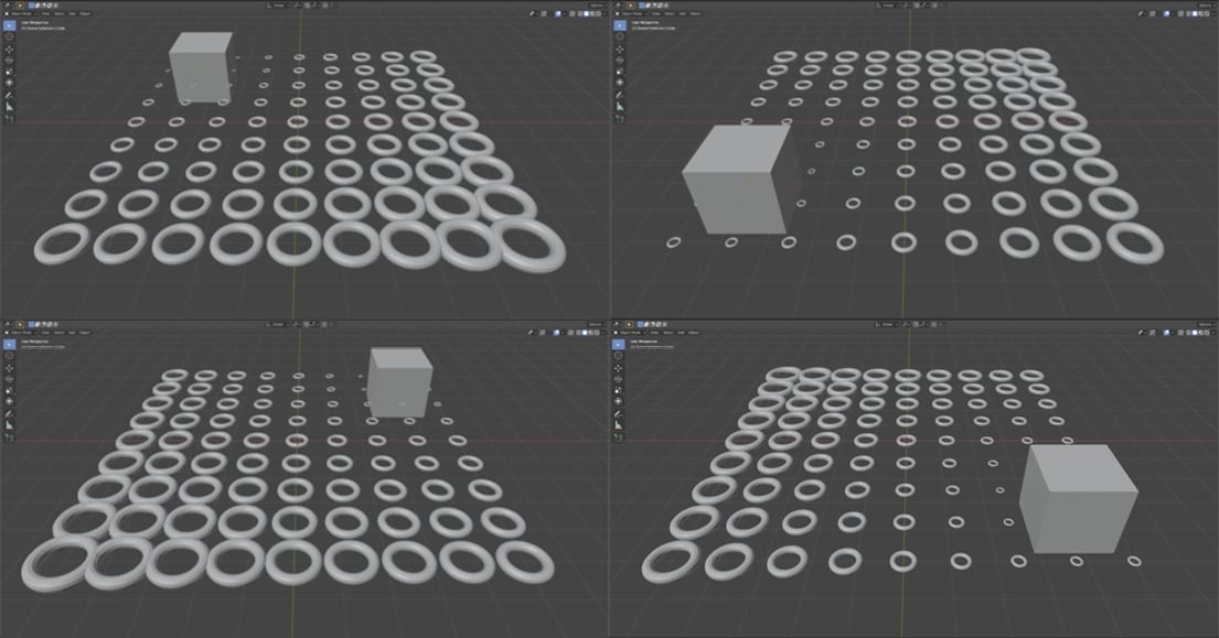
Figure 1.47 – Your first Geometry Nodes scene that animates dynamically
Using this method, you can easily create interesting and dynamic motion graphics scenes inside of Blender. Experiment with this technique and try to affect the rotation or position of your instance objects rather than their scale. Have fun creating interesting animations!