
In this recipe, we will deform a planar mesh using the vertex shader. We know that the vertex shader is responsible for outputting the clip space position of the given object space vertex. In between this conversion, we can apply the modeling transformation to transform the given object space vertex to world space position.
For this recipe, we assume that the reader knows how to set up a simple triangle on screen using a vertex and fragment shader as detailed in the previous recipe. The code for this recipe is in the Chapter1\RippleDeformer directory.
We can implement a ripple shader using the following steps:
Define the vertex shader that deforms the object space vertex position.
#version 330 core
layout(location=0) in vec3 vVertex;
uniform mat4 MVP;
uniform float time;
const float amplitude = 0.125;
const float frequency = 4;
const float PI = 3.14159;
void main()
{
  float distance = length(vVertex);
  float y = amplitude*sin(-PI*distance*frequency+time);
  gl_Position = MVP*vec4(vVertex.x, y, vVertex.z,1);
}
Define a fragment shader that simply outputs a constant color.
#version 330 core
layout(location=0) out vec4 vFragColor;
void main()
{
  vFragColor = vec4(1,1,1,1);
}
Load the two shaders using the
GLSLShaderclass in theOnInit()function.shader.LoadFromFile(GL_VERTEX_SHADER, "shaders/shader.vert"); shader.LoadFromFile(GL_FRAGMENT_SHADER, "shaders/shader.frag"); shader.CreateAndLinkProgram(); shader.Use(); shader.AddAttribute("vVertex"); shader.AddUniform("MVP"); shader.AddUniform("time"); shader.UnUse();Create the geometry and topology.
int count = 0;
int i=0, j=0;
for( j=0;j<=NUM_Z;j++) {
  for( i=0;i<=NUM_X;i++) {
    vertices[count++] = glm::vec3( ((float(i)/(NUM_X-1)) *2-1)* HALF_SIZE_X, 0, ((float(j)/(NUM_Z-1))*2-1)*HALF_SIZE_Z);
  }
}
GLushort* id=&indices[0];
for (i = 0; i < NUM_Z; i++) {
  for (j = 0; j < NUM_X; j++) {
    int i0 = i * (NUM_X+1) + j;
    int i1 = i0 + 1;
    int i2 = i0 + (NUM_X+1);
    int i3 = i2 + 1;
    if ((j+i)%2) {
      *id++ = i0; *id++ = i2; *id++ = i1;
      *id++ = i1; *id++ = i2; *id++ = i3;
    } else {
      *id++ = i0; *id++ = i2; *id++ = i3;
      *id++ = i0; *id++ = i3; *id++ = i1;
    }
  }
}
Store the geometry and topology in the buffer object(s).
glGenVertexArrays(1, &vaoID);
glGenBuffers(1, &vboVerticesID);
glGenBuffers(1, &vboIndicesID);
glBindVertexArray(vaoID);
glBindBuffer (GL_ARRAY_BUFFER, vboVerticesID);
glBufferData (GL_ARRAY_BUFFER, sizeof(vertices), &vertices[0], GL_STATIC_DRAW);
glEnableVertexAttribArray(shader["vVertex"]);
glVertexAttribPointer(shader["vVertex"], 3, GL_FLOAT, GL_FALSE,0,0);
glBindBuffer(GL_ELEMENT_ARRAY_BUFFER, vboIndicesID);
glBufferData(GL_ELEMENT_ARRAY_BUFFER, sizeof(indices), &indices[0], GL_STATIC_DRAW);
Set up the perspective projection matrix in the resize handler.
P = glm::perspective(45.0f, (GLfloat)w/h, 1.f, 1000.f);
Set up the rendering code to bind the
GLSLShadershader, pass the uniforms and then draw the geometry.void OnRender() { time = glutGet(GLUT_ELAPSED_TIME)/1000.0f * SPEED; glm::mat4 T=glm::translate(glm::mat4(1.0f), glm::vec3(0.0f, 0.0f, dist)); glm::mat4 Rx= glm::rotate(T, rX, glm::vec3(1.0f, 0.0f, 0.0f)); glm::mat4 MV= glm::rotate(Rx, rY, glm::vec3(0.0f, 1.0f, 0.0f)); glm::mat4 MVP= P*MV; shader.Use(); glUniformMatrix4fv(shader("MVP"), 1, GL_FALSE, glm::value_ptr(MVP)); glUniform1f(shader("time"), time); glDrawElements(GL_TRIANGLES,TOTAL_INDICES,GL_UNSIGNED_SHORT,0); shader.UnUse(); glutSwapBuffers(); }Delete the shader and other OpenGL objects.
void OnShutdown() {
  shader.DeleteShaderProgram();
  glDeleteBuffers(1, &vboVerticesID);
  glDeleteBuffers(1, &vboIndicesID);
  glDeleteVertexArrays(1, &vaoID);
}
In this recipe, the only attribute passed in is the per-vertex position (vVertex). There are two uniforms: the combined modelview projection matrix (MVP) and the current time (time). We will use the time uniform to allow progression of the deformer so we can observe the ripple movement. After these declarations are three constants, namely amplitude (which controls how much the ripple moves up and down from the zero base line), frequency (which controls the total number of waves), and PI (a constant used in the wave formula). Note that we could have replaced the constants with uniforms and had them modified from the application code.
Now the real work is carried out in the main function. We first find the distance of the given vertex from the origin. Here we use the length built-in GLSL function. We then create a simple sinusoid. We know that a general sine wave can be given using the following function:
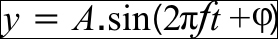
Here, A is the wave amplitude, f is the frequency, t is the time, and φ is the phase. In order to get our ripple to start from the origin, we modify the function to the following:
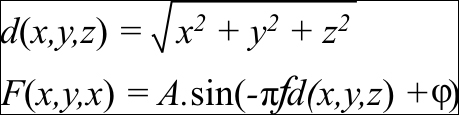
In our formula, we first find the distance (d) of the vertex from the origin by using the Euclidean distance formula. This is given to us by the length built-in GLSL function. Next, we input the distance into the sin function multiplying the distance by the frequency (f) and (π). In our vertex shader, we replace the phase (φ) with time.
#version 330 core
layout(location=0) in vec3 vVertex;
uniform mat4 MVP;
uniform float time;
const float amplitude = 0.125;
const float frequency = 4;
const float PI = 3.14159;
void main()
{
  float distance = length(vVertex);
  float y = amplitude*sin(-PI*distance*frequency+time);
  gl_Position = MVP*vec4(vVertex.x, y, vVertex.z,1);
}
After calculating the new y value, we multiply the new vertex position with the combined modelview projection matrix (MVP). The fragment shader simply outputs a constant color (in this case white color, vec4(1,1,1,1)).
#version 330 core
layout(location=0) out vec4 vFragColor;
void main()
{
   vFragColor = vec4(1,1,1,1);
}Similar to the previous recipe, we declare the GLSLShader object in the global scope to allow maximum visibility. Next, we initialize the GLSLShader object in the OnInit() function.
shader.LoadFromFile(GL_VERTEX_SHADER, "shaders/shader.vert");
shader.LoadFromFile(GL_FRAGMENT_SHADER,"shaders/shader.frag");
shader.CreateAndLinkProgram();
shader.Use();
  shader.AddAttribute("vVertex");
  shader.AddUniform("MVP");
  shader.AddUniform("time");
shader.UnUse();
The only difference in this recipe is the addition of an additional uniform (time).
We generate a simple 3D planar grid in the XZ plane. The geometry is stored in the vertices global array. The total number of vertices on the X axis is stored in a global constant NUM_X, whereas the total number of vertices on the Z axis is stored in another global constant NUM_Z. The size of the planar grid in world space is stored in two global constants, SIZE_X and SIZE_Z, and half of these values are stored in the HALF_SIZE_X and HALF_SIZE_Z global constants. Using these constants, we can change the mesh resolution and world space size.
The loop simply iterates (NUM_X+1)*(NUM_Z+1) times and remaps the current vertex index first into the 0 to 1 range and then into the -1 to 1 range, and finally multiplies it by the HALF_SIZE_X and HALF_SIZE_Z constants to get the range from –HALF_SIZE_X to HALF_SIZE_X and –HALF_SIZE_Z to HALF_SIZE_Z.
The topology of the mesh is stored in the indices global array. While there are several ways to generate the mesh topology, we will look at two common ways. The first method keeps the same triangulation for all of the mesh quads as shown in the following screenshot:
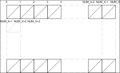
This sort of topology can be generated using the following code:
GLushort* id=&indices[0];
for (i = 0; i < NUM_Z; i++) {
  for (j = 0; j < NUM_X; j++) {
    int i0 = i * (NUM_X+1) + j;
    int i1 = i0 + 1;
    int i2 = i0 + (NUM_X+1);
    int i3 = i2 + 1;
    *id++ = i0; *id++ = i2; *id++ = i1;
    *id++ = i1; *id++ = i2; *id++ = i3;
  }
}
The second method alternates the triangulation at even and odd iterations resulting in a better looking mesh as shown in the following screenshot:
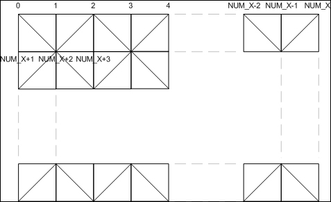
In order to alternate the triangle directions and maintain their winding order, we take two different combinations, one for an even iteration and second for an odd iteration. This can be achieved using the following code:
GLushort* id=&indices[0];
for (i = 0; i < NUM_Z; i++) {
  for (j = 0; j < NUM_X; j++) {
    int i0 = i * (NUM_X+1) + j;
    int i1 = i0 + 1;
    int i2 = i0 + (NUM_X+1);
    int i3 = i2 + 1;
    if ((j+i)%2) {
      *id++ = i0; *id++ = i2; *id++ = i1;
      *id++ = i1; *id++ = i2; *id++ = i3;
    } else {
      *id++ = i0; *id++ = i2; *id++ = i3;
      *id++ = i0; *id++ = i3; *id++ = i1;
    }
  }
}
After filling the vertices and indices arrays, we push this data to the GPU memory. We first create a vertex array object (vaoID) and two buffer objects, the GL_ARRAY_BUFFER binding for vertices and the GL_ELEMENT_ARRAY_BUFFER binding for the indices array. These calls are exactly the same as in the previous recipe. The only difference is that now we only have a single per-vertex attribute, that is, the vertex position (vVertex). The OnShutdown() function is also unchanged as in the previous recipe.
The rendering code is slightly changed. We first get the current elapsed time from freeglut so that we can move the ripple deformer in time. Next, we clear the color and depth buffers. After this, we set up the modelview matrix. This is carried out by using the matrix transformation functions provided by the glm library.
glm::mat4 T=glm::translate(glm::mat4(1.0f),
glm::vec3(0.0f, 0.0f, dist));
glm::mat4 Rx= glm::rotate(T,  rX, glm::vec3(1.0f, 0.0f, 0.0f));
glm::mat4 MV= glm::rotate(Rx, rY, glm::vec3(0.0f, 1.0f,  0.0f));
glm::mat4 MVP= P*MV;
Note that the matrix multiplication in glm follows from right to left. So the order in which we generate the transformations will be applied in the reverse order. In our case the combined modelview matrix will be calculated as MV = (T*(Rx*Ry)). The translation amount, dist, and the rotation values, rX and rY, are calculated in the mouse input functions based on the user's input.
After calculating the modelview matrix, the combined modelview projection matrix (MVP) is calculated. The projection matrix (P) is calculated in the OnResize() handler. In this case, the perspective projection matrix is used with four parameters, the vertical fov, the aspect ratio, and the near and far clip plane distances. The GLSLShader object is bound and then the two uniforms, MVP and time are passed to the shader program. The attributes are then transferred using the glDrawElements call as we saw in the previous recipe. The GLSLShader object is then unbound and finally, the back buffer is swapped.
In the ripple deformer main function, we attach two new callbacks; glutMouseFunc handled by the OnMouseDown function and glutMotionFunc handled by the OnMouseMove function. These functions are defined as follows:
void OnMouseDown(int button, int s, int x, int y) {
  if (s == GLUT_DOWN)  {
    oldX = x;
    oldY = y;
  }
  if(button == GLUT_MIDDLE_BUTTON)
  state = 0;
  else
  state = 1;
}
This function is called whenever the mouse is clicked in our application window. The first parameter is for the button which was pressed (GLUT_LEFT_BUTTON for the left mouse button, GLUT_MIDDLE_BUTTON for the middle mouse button, and GLUT_RIGHT_BUTTON for the right mouse button). The second parameter is the state which can be either GLUT_DOWN or GLUT_UP. The last two parameters are the x and y screen location of the mouse click. In this simple example, we store the mouse click location and then set a state variable when the middle mouse button is pressed.
The OnMouseMove function is defined as follows:
void OnMouseMove(int x, int y) {
  if (state == 0)
    dist *= (1 + (y - oldY)/60.0f);
  else {
    rY += (x - oldX)/5.0f;
    rX += (y - oldY)/5.0f;
  }
  oldX = x; oldY = y;
  glutPostRedisplay();
}
The OnMouseMove function has only two parameters, the x and y screen location where the mouse currently is. The mouse move event is raised whenever the mouse enters and moves in the application window. Based on the state set in the OnMouseDown function, we calculate the zoom amount (dist) if the middle mouse button is pressed. Otherwise, we calculate the two rotation amounts (rX and rY). Next, we update the oldX and oldY positions for the next event. Finally we request the freeglut framework to repaint our application window by calling glutPostRedisplay() function. This call sends the repaint event which re-renders our scene.
In order to make it easy for us to see the deformation, we enable wireframe rendering by calling the glPolygonMode(GL_FRONT_AND_BACK, GL_LINE) function in the OnInit() function.
Tip
There are two things to be careful about with the glPolygonMode function. Firstly, the first parameter can only be GL_FRONT_AND_BACK in the core profile. Secondly, make sure that the second parameter is named GL_LINE instead of GL_LINES which is used with the glDraw* functions. To disable the wireframe rendering and return to the default fill rendering, change the second parameter from GL_LINE to GL_FILL.
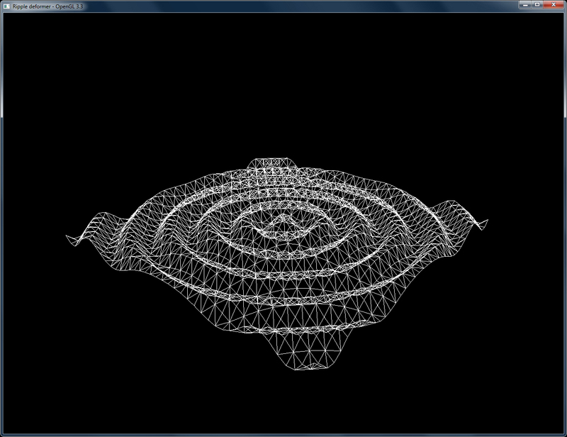
Running the demo code shows a ripple deformer propagating the deformation in a mesh grid as shown in the following screenshot. Hopefully, this recipe should have cleared how to use vertex shaders, especially for doing per-vertex transformations.