

We will start with the wall tool to create the main exterior walls on the 1st floor of our house, and then create the floor with the slab tool. However, before we begin, let's make sure your Renovation Filter is set to New Construction.
The Renovation Filter is an active setting that controls how the elements you create are displayed. Everything we create in this project is for new construction so we need the new construction filter to be active.
To do so, go to the Document menu, click on Renovation and then click on 04 New Construction.
The Wall tool has settings for height, width, composite, layer, pen weight and more. We will learn about these things as we go along, and learn a little bit more each time we progress into to the project.
To create the exterior walls of the 1st story perform the following steps:
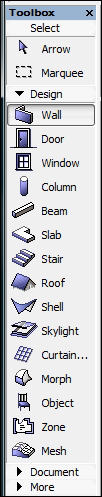
Select the Wall tool from the Toolbox palette, or from the menu bar under Design | Design Tools | Wall.
Double click on 1. 1st Story in the Navigator palette to ensure that we are working on story 1.
Select the Wall tool from the Toolbox palette, or from the menu bar under Design | Design Tools | Wall.

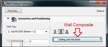
Change the composite type to be Siding 2x6 Wd. Stud. Click on the wall composite button to do this.
Notice at the bottom of the Wall Default Settings window is the layer currently assigned to the wall tool. It should be set to A-WALL-EXTR.
Click on OK to start your first wall.
Click near the center of the drawing screen and move your cursor to the left, notice the orange dashed line that appears. That is your guide line. Keep your cursor over the guide line so that it keeps you locked in the orthogonal direction. You should also immediately see the Tracker palette pop up, displaying your distance drawn and angle after your first click. Before you make your second click, enter the number
24from your keyboard and press Enter. You should now have 24-0" long wall.Select this again and make your first click on the upper left end corner of your first wall. Move your cursor down, so that it snaps to the guideline, enter the number
28, and press the Enter key.Draw your third wall by clicking on the bottom left endpoint of your second wall, move your cursor to the right, snapped over the guide line, type in the number
24and press Enter.Draw your fourth wall by clicking on the bottom right end point of your third wall and the starting point of your first wall. You should now have four walls that measure 24'-0" x 28"-0, outside edge to outside edge.
Move your four walls to the center of the drawing view and perform the following steps:
a. Click on the Arrow tool at the top of the Toolbox.
b. Click outside one of the corners of the walls, and then click on the opposite side. All four walls should be selected now.
c. Use the
Dragcommand to move the walls. The quickest way to activate theDragcommand is by pressing Ctrl + D. The long way is from the menu bar by navigating to Edit | Move | Drag.d. Drag (move) the walls to the center of your drawing window.
e. Press the Esc key or click on a blank space in your drawing window to deselect the walls.

You are now ready to create a floor with the slab tool. But first, let's have a little fun and see how it looks in 3D (press the F3 key):
From the Navigator palette, double click on Generic Axonometry under the 3D folder icon.
This will open a 3D view window. Hold your Shift key down, press down on your scroll wheel button, and slowly move your mouse around. You are now orbiting!
Play around with it a little, then get back to work and go to the next step to create your first floor slab. Press the F2 key to get back to a 2D view.
The slab tool is used to create floors. It is also used to create ceilings. We will begin using it now to create the first floor for our house. Similar to the Wall tool, it also has settings for layer, pen weight and composite. To create the first story's floor using the Slab tool, perform the following steps:
Select the Slab tool from the Toolbox palette or from the menu bar under Design | Design Tools | Slab.
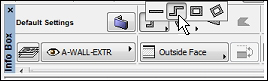
This will change the contents of the Info Box palette. Click on the Slab icon in Info Box. This will bring up the Slab Default Settings (active properties) window for the Slab tool.
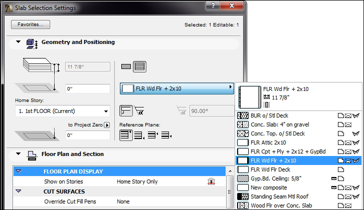
As with the Wall tool, you have a composite setting for the slab tool. Set the composite type for the slab tool to FLR Wd Flr + 2x10.
The layer should be set to A-FLOR.
Click OK.
You could draw the shape of the slab by tracing over the outside lines of your walls but we are going to use the Magic Wand feature. Hover your cursor over the space inside your four walls and press the space bar on your keyboard. This will automatically create the slab using the boundary created by the walls. Then, open a 3D view and look at your floor.
We could repeat all of the previous steps to create the floor and walls for the second story and the basement, but in this case, it will be quicker to copy what we have already drawn on the first story and copy it up with the Edit Elements by Stories tool. Perform the following steps to create the exterior walls and floor slabs for the basement and second story:
Go to the Navigator palette and right click over Stories, select Edit Elements by Stories. The Edit Elements by Stories window will open.
Under Select Action, you want to set it to Copy.
Under From Story, set it to 1. 1st FLOOR.
In the To Story section, check the box for 2nd FLOOR and -1. BASEMENT.
Click on OK.
You should see a dialog box appear, stating that as a result of the last operation, elements have been created and/or have changed their position on currently unseen stories. Whenever you get this message, you should confirm that you have not created any unwanted elements.
The floor and the walls on the BASEMENT story need to be changed to a different composite type. Do this by performing the following steps:
Open the BASEMENT view and select the four walls by clicking on one at a time while holding down the Shift key.
Right click over your selection and click on Wall Selection Settings. Change the walls to the EIFS on 8" CMU composite type. Then, click on OK.
Move your cursor over the floor slab. The quick selection cursor should appear. This selection mode allows you to click on an object without needing to find an edge or endpoint. Click on the slab.
Open the Slab Selection Setting window but this time, do it by pressing the Ctrl + T key combination. Change the floor slab composite to Conc. Slab: 4" on gravel. Click on OK.
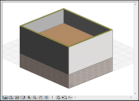
Open a 3D view (by pressing the F3 key) and orbit around your house. It should look similar to the following screenshot:
We need to add the garage and the laundry room, which connects the garage to the house. Do this by performing the following steps:
Open the 1st FLOOR story from the project map.
Start the Wall tool. From the Info Box palette, set the wall composite setting to Siding 2x6 Wd. Stud.
Click on the upper-left corner of your house for your wall starting point. Move your cursor to the left, snap to the guide line, type
6'-10", and press Enter.Change the Geometry Method setting on Info Box to Chained. Refer to the following screenshot:
Start your next wall by clicking on the endpoint of your last wall, move your cursor up, snap to the guideline and type 5', and press Enter.
Move your cursor to the left, snap to grid line, type in
12'-6", and press Enter.Move your cursor down, snap to grid line, type in
22'-4", and press Enter.Move your cursor to the right, snap to grid line and double click on the perpendicular west wall (double pressing your Enter key will work the same as a double click).
Now we want to create the floor for this new set of walls. To do that, perform the following steps:
Start the Slab tool.
Change the composite to Conc. Slab: 4" on gravel.
Hover your cursor inside the new set of walls and press the Space key to use the magic wand. This will create the floor slab for the garage and laundry room.
There is still one more wall to create, but this time we will use the Adjust command to, in effect, create a new wall:
Select the 5'-0" wall drawn in the previous exercise.
Go to the Edit menu, click on Reshape, and then click on Adjust.
Click on the bottom edge of the perpendicular wall down below. The wall should extend down. Refer to the following screenshot:

Then Change to a 3D view (by pressing F3) and examine your work.
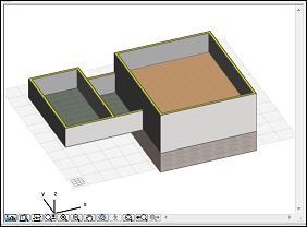
The 3D view