
The Stair tool is a tool that involves a good amount of setup before you actually place a stair, because stairs are always unique and contain many components. For our project we need 2 stairs. One to get to the 2nd floor from the first floor and one to get to the basement from the first floor.
Before we get started, we will want to alter our view to give us a better view. Specifically, we want to turn off the window and door tags. We will do this by changing the current model view options:
Go to the menu bar, navigate to Document | Set Model View | Model View Options.
Select the Presentation-Solid model view option combination.
Click on OK.
Perform the following steps to create your first stair:
Open the basement viewpoint from the project map on the Navigator palette. Toggle on the Trace feature from the Standard tool bar at the top of your screen. Turn on the first floor for tracing.
a. Click the drop down portion of the Trace button, and select Reference | Above Current Story.
Start the Stair tool. Set the construction method to Diagonal and the Home story to -1. BASEMENT on the Info Box palette.
Click on the Stair icon to open the Stair Default Setting window. Change the stair type to Stair Straight 19. Then, go to the Preview and Position section. Then, perform the following steps:
a. Rotate the preview to match the image that follows.
b. Set the insertion point to the lower right corner of the stair.
c. Uncheck the Mirror Library Part box.
d. Change the height to
9'. Click on OK.
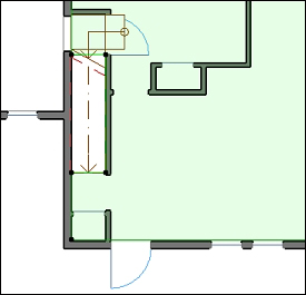
You will make two clicks to define the width and length of the stair. Click on the inside corner of the opening above for your first click and the bottom edge of the door above, as per the image that follows:

Toggle off the trace and your plan should look similar to the following image.
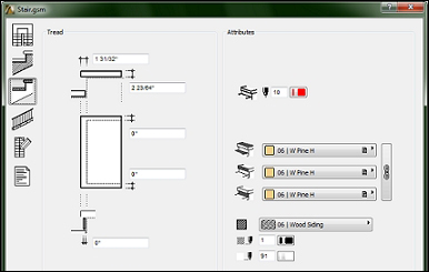
Click on the Structure and Landing settings button on the left-hand side.
a. Change all four surface materials under Attributes to 06 | W Pine H.
b. Change the section fill to vectorial fill 06 | Wood Siding.

Click on the Tread Settings button on the left.
a. Change all three surface materials under Attributes to 06 | W Pine H.
b. Change the section fill to vectorial fill 06 | Wood Siding.
c. Click on the Railing Settings button on the left-hand side.
d. Change the Railing Setting selection to No railing.
e. Click on the Symbol Settings button to the left.
f. Change the 2D Detail Level type to Type 9.
g. Click on OK. The Save Stair window will open, prompting you to name your new stair. Enter the name
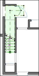
Stair Custom 1and click on Save.Click on the 1st Floor plan view to insert the stair. Then, drag it into position as shown in the following diagram:
The stair going up to the second floor is not of a typical design. It is an L-shaped stair with a landing. The landing is at the top and the L portion is only 2 risers. In this situation we will use the Create Stair tool to create a new stair object. Perform the following steps to create your second stair:
Open the 1st FLOOR view. Click on the Stair tool icon in the Toolbox palette. Then from the Info Box palette, click on the Create Stair button.
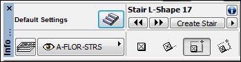
Select L-Run with Landing. Click on OK.

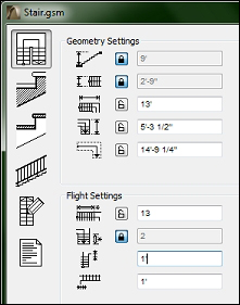
This will open a settings window. The Geometry and Flight settings will be shown. Make the following changes:
a. Total height:
9'| push the lock button.b. Flight width:
2'-9"| push the lock button.c. Lower part length:
13'.d. Number of risers of the lower side to
13.e. Number of risers of the upper side to
2| push the lock button.f. Offset of lower walking:
1'.g. Offset of upper walking:
1'.
In order for the stairs to get from the first floor to the second floor, you will need to cut a hole in the floor slab on the second floor. Now that you have modelled all the interior walls, you have a template to use as a guide to make the hole.
Open the 2nd Floor viewpoint from the project map. Toggle on the Trace feature and change the reference to 1st Floor.
Make sure the bathroom entry door is placed at the far right, up against the wall.
Start the Slab tool and then select the floor slab (it is vital that the Slab tool is active while the slab is selected). Change the construction method to Polygon.
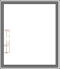
In this step we will define the boundary of the hole to be cut in the slab. Make your first click on the bottom edge of the bathroom wall, where it intersects the stair below. Trace the outline of the stair below and along the edge of the second floor walls as shown in the following diagram. Toggle off the Trace feature and your floor should as in the following diagram:

Do the same for the floor on the first floor according to the diagram that follows. This will allow access to the basement stair to reach the first floor.