
3D is all about the third Z coordinate. In 2D, we only care for the X and Y axes, but never used the Z axis. And most of the time, we don't even use coordinates, just the top-twenty AutoCAD commands, the Ortho tool, and so on. But in 3D, the correct use of coordinates can substantially accelerate our work. We will first briefly cover how to introduce points by coordinates and how to extrapolate to the third dimension.
The location of all entities in AutoCAD is related to a coordinate system. Any coordinate system is characterized by an origin and positive directions for the X and Y axes. The Z axis is obtained directly from the X and Y axes by the right-hand rule: if we rotate the right hand from the X axis to the Y axis, the thumb indicates the positive Z direction.
Picture that when prompting for a point; besides specifying it in the drawing area with a pointing device such as a mouse, we can enter coordinates using the keyboard.
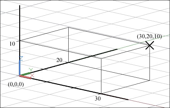
The format for the absolute Cartesian coordinates related to the origin is defined by the values of the three orthogonal coordinates, namely, X, Y, and Z, separated by commas:
X coordinate, Y coordinate, Z coordinate
The Z coordinate can be omitted.
For instance, if we define a point with the absolute coordinates 30, 20, and 10, this means 30 absolute is in the X direction, 20 is in the Y direction, and 10 is in the Z direction.
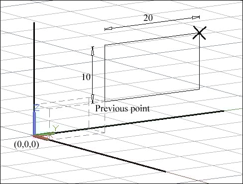
Frequently, we want to specify a point in the coordinates, but one that is related to the previous point. The format for the relative Cartesian coordinates is defined by the symbol AT (@), followed by increment values in the three directions, separated by commas:
@X increment, Y increment, Z increment
Of course, one or more increments can be 0. The Z increment can be omitted.
For instance, if we define a point with relative coordinates, @0,20,10, this means in relation to the previous point, 0 is in X, 20 is in Y, and 10 is in Z directions.
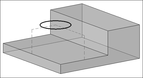
When we want to specify a point but decompose it step-by-step, that is, separate its coordinates based on different locations, we may use filters. When prompting for a point, we access filters by digitizing the X, Y, or Z axes for individual coordinates, or XY, YZ, or ZX for pairs of coordinates. Another way is from the osnap menu, CTRL + mouse right-click, and then Point Filters. AutoCAD requests for the remaining coordinates until the completion of point definition.
Imagine that we want to specify a point, for instance, the center of a circle, where its X coordinate is given by the midpoint of an edge, its y coordinate is the midpoint of another edge, and finally its Z coordinate is any point on a top face. Assuming that Midpoint osnap is predefined, the dialog should be:
Command: CIRCLE
Specify center point for circle or [3P/2P/Ttr (tan tan radius)]: .X
of midpoint of edge
(need YZ): .Y
of midpoint of edge
(need Z): any point on top face
Specify radius of circle or [Diameter]: value