

The scene doesn't look realistic with just a hole in the wall. Let's make a window using SketchUp's Push/Pull tool. It will help if you hide the wall and ceiling now. This will allow you to view the room more easily as you progress with the tutorial. You will reinstate them later when they are needed again.
Zoom and rotate out to a bird's eye view of the room.
Select the wall face to the left of the window and the ceiling.
Right-click on one of them and select Hide from the context menu, as shown in the following screenshot:

To create a window reveal efficiently, we have to be a bit creative with the tools that SketchUp offers:
First, use the Line tool (Draw | Line) to draw along the edge of the existing window opening. Make sure that you snap to the endpoints (corners) at the beginning and end of the line.
As soon as the line is completed, SketchUp will close the opening with a new rectangle. Use the Push/Pull tool to push the new rectangle outwards by about 200 mm. This will create a reveal for the window.
Delete the window rectangle again. As you see, the fastest way to create the four sides for the reveal is to create and extrude an extra rectangle that we do not need.
With the Line tool, draw a line out from the edge of the bottom window along the green axis, then down along the blue axis, back to the wall, and back to the start, as shown at the left in the following image.
Select the Arc tool from the Draw menu. Draw an arc as shown in the following image; then, delete the corners with the Erase tool (middle of the following image).
Use the Push/Pull tool to extrude the shape along the bottom of the window in the first part of the image and then from the other direction to form a windowsill, as shown in the following image:

Select the Rectangle tool and move the cursor along the top corner of the window. When you see a Tooltip saying Midpoint, click and draw a rectangle across the lintel.
Use the Arc tool to round off the front and delete the corners as you did earlier.
Use the Push/Pull tool again to extrude the shape down to span the whole window frame.
Create the glass pane by selecting the midpoint of one corner and then the opposite corner with the Rectangle tool, as shown at the right of the following image:

Select this rectangle and apply the Translucent_Glass_Blue material from the Translucent collection with the Paint Bucket tool on both sides of the rectangle (inside and outside). Your scene should now look similar to the following screenshot:

If any wall faces have turned blue, select them now. Right-click on them and select Reverse Faces from the context menu.
Reinstate the hidden faces by navigating to Edit | Unhide | All.
Check if these faces also need reversing.
Double-click on the Scene 1 tab to reset the view to the interior of the room.
For the artwork on the wall, you can simply grab some images of your own or browse the Web. For this tutorial, it doesn't matter where you get them from. However, if you have some art of your own, why not scan or photograph it and use it here? It can be your own 3D portfolio!
Select Import from the File menu.
Change the Files of type: option to All Supported Image Types.
Choose an image you want to use for your artwork.
Now, move the cursor to the wall and click on it to set the bottom-left corner of the image. Stretch the image to the size you want and click on the wall again, as shown in the following screenshot:

Repeat this for more images. Remember to click on the Scene 1 tab from time to time so that you can see what will or will not be in the frame when you render.
Trace a rectangle around each image. You can snap to the corners of the images to draw accurately.
Finally use the Push/Pull tool to give each canvas some depth. You can see the canvas edge in the following image:

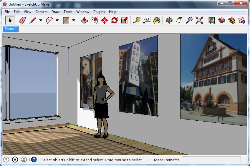
Click on the Scene 1 tab to check your scene from the camera's position. You should have something similar to the following screenshot. Move the person around a bit to give her a better view or remove her altogether if you prefer:
We are already in good shape with our scene. So, the first thing we should do is a test rendering:
Navigate to Plugins | Thea Render | Thea Rendering Window to open the main rendering window within SketchUp.
Below the main window area, you will find the rendering controls. Check if the Mode is set to Unbiased (TR1) on the Rendering tab.
Now, just click on the Start button in the middle (the triangle pointing to the right) to export the scene and get the rendering started.
After a short time, the rendering will appear and will improve gradually. Most likely, it is going to be too dark to see anything, though. While the rendering is still continuing, you can adjust the brightness of the image:
Switch to the Display tab.
Adjust the setting for ISO to 800 or 1600.

Give it a bit of time to render until you have a good idea of the light and reflections; then hit the Stop button at the far right. You should notice the following:
The image aspect ratio is different from the SketchUp view
The floor is not as reflective as we would expect from a polished laminate
The light is diffused near the window, and the shadows are not sharp as we see in SketchUp
This is not too surprising since at the moment, all materials have the same properties (except for the window that is translucent). To improve the image, we have to define some additional properties for the materials.
In order to produce photorealistic images, we need to improve the optical characteristics of the SketchUp materials. Without any special assignment, SketchUp materials get translated into a default material that only maintains the color and texture from SketchUp. To define advanced properties, we can use the Thea Tool window:
Open the Thea Tool window by navigating to the Plugins | Thea Render menu.
On the Camera tab, change the Aspect ratio to SU Window.
Click on the Materials tab. You will see the materials dialog shown in the following screenshot:

In the drop-down menu at the top, select the Translucent_Glass_Blue material. This is the material we used for the window.
In the drop-down menu below the preview area, select Thin Glass.
Click on the SU button to the right of the Color label. A new (blue) button will appear next to it.
Click on it to open a color selector.
Pick a white color from the palette and click on OK to close the selector.
You can leave the remaining options for the glass material as they are.
Next, select the material you used for the floor (Wood_Floor_Light in our case).
In the second drop-down, pick Thea Material (Mat-Lab).
The Thea Material Lab window will open and show a preview of the material as it is. You can see this in the following screenshot:
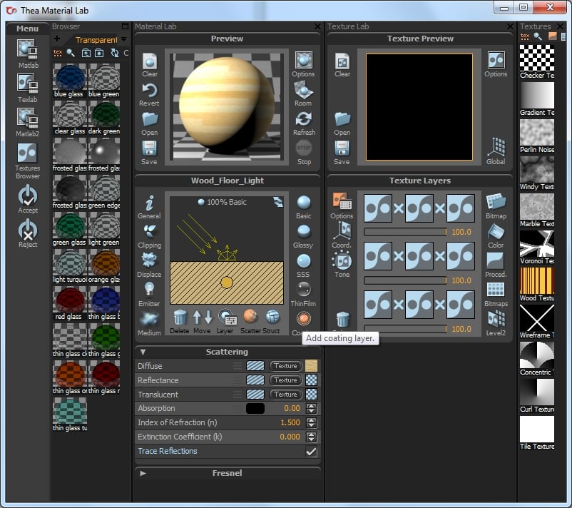
Below the Preview panel, you will find the material properties panel. Find the Coating button in the bottom-right corner of the window and click on it (only once!).
A new layer will be added to the material built up, and the preview window should update in a short time. You can see the change in specular highlights in the preview.
Click on the Accept button to the left of the Material Lab window to apply your changes and close the window.
Finally select the carpet material (Carpet_Pattern_LeafSpares_Tan).
Select Matte as Thea material type.
Increase the Bump value to 50%.
With these changes, we have addressed the issues we noticed in our first test render. We are ready to give it another go!
Open the Thea Rendering Window again.
Check if the rendering mode is still set to Unbiased (TR1).
Press the Start button. The scene will be exported again, and a new rendering process starts.
Let the rendering continue for a while until you can make out a few more details.
If you find that the rendering is too bright or too dark, switch to the Display tab.
Adjust the ISO, Shutter, and f-number settings until the image is reasonably lit. You can see a possible combination in the following screenshot:

When the image quality has progressed sufficiently, you can check the issues we noted earlier. You see that the sunlight through the window is now clearly defined; there is a bit of specular reflection visible on the floor, and the carpet does not seem to reflect the light anymore.
The rendered image will progress in the render window. With each new pass, the image will look a bit better. The unbiased rendering process will continue like this but it will never finish. You can set Limits for Time or Samples on the Rendering tab to terminate the rendering after a specific time, but you can also just stop the calculations when you think that the quality of the image is sufficient:
Either wait for your Limit to be reached, or click on the Stop button to interrupt the rendering.
Click on the Save Image button at the far left of the screen, and choose a name and file type for the rendered image. PNG is usually ok.