
To start sending data between your XBee modules, they all have to be joined to the same network first. In the previous examples, you have used a single coordinator and router, which together have automatically formed a network. In this section, you will learn a bit more about how these networks are formed and how addressing works.
The ZigBee protocol defines three different device types: coordinator, router, and end device. These are explained next:
A coordinator starts a network and allows other devices to join it. It otherwise acts as a normal router. Each network must have exactly one coordinator.
A router joins an existing network and will forward (route) packets on behalf of other members in the network, creating a mesh network. However, to maintain this routing functionality, routers cannot enter sleep mode and should usually be mains-powered.
An end device is more limited: it cannot do routing itself, instead relying on a router (or the coordinator) to route its messages to their destination. Unlike routers, end devices can sleep to save power.
A typical network might look like this:
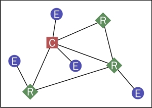
Note that the coordinator and routers can talk to each other (when they are close enough), but each end device can only talk to a single router (or the coordinator).
In the first chapters, you will use a single coordinator and one or more routers. In Chapter 6, Finishing Touches, end devices will be discussed in more detail.
In ZigBee, a network is identified by a PAN (Personal Area Network) identifier. When a coordinator is first started with its default settings, it will automatically start a new, unencrypted network by selecting a random PAN ID and a random channel. When a router or end device module starts, it will start scanning all channels for existing networks that allow new modules to join, select one, and join it. In the default configuration, coordinators and routers allow new devices to join the network without restriction.
There are a few related read-only configuration values supported, shown under the Networking category in XCTU:
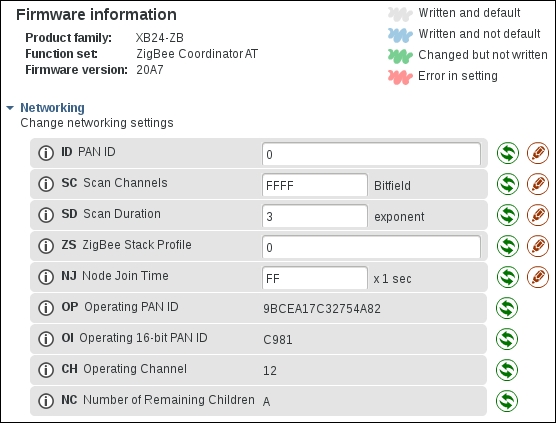
In the preceding screenshot, you can see the OP value. This is the Operating PAN ID: the PAN ID of the network created by the coordinator (or, on a router or end device, the PAN ID of the network successfully joined). The CH Operating Channel value shows the channel number selected by the coordinator (you might need to click on the Refresh button at the top to see the most recent values here).
Note that there is a second operating PAN ID here: OI. OP is a 64-bit long version, which is used in scan requests, beacons, and network joining, but OI is a 16-bit short version, which is used in most packets to save transmission time. If two different networks happen to have selected the same 16-bit PAN ID, the network can detect this and the conflict can be resolved by switching to a new 16-bit PAN ID. The 64-bit PAN ID will never change (unless of course the coordinator leaves the network, starts a new one, and ID is not set).
Also note the ID configuration value. This allows preconfiguring the 64-bit PAN ID on your modules by using a non-zero value. On a coordinator, this means the started network gets this 64-bit PAN ID. On routers and end devices, this means that the module will only join networks with a matching PAN ID and will ignore all others. Preconfiguring a PAN ID can help to prevent unexpected behavior (consider the case where your neighbor is also running a ZigBee network, and your nodes are joining his network instead of yours).
Go ahead and select some random 64-bit number for your network. This can be some easy to remember number, or whatever you like (unlike encryption keys, there is no security benefit of having a true random number here). Configure this number in the ID configuration value on both nodes. Changing the ID value on your modules will automatically cause them to leave their current network and create (or try to join) a new network.
You will see that, after this (and refreshing the configuration values in XCTU), the OP value (Operating 64-bit PAN ID) is set to the value you configured, but the OI value (Operating 16-bit PAN ID) is now different from before.
In addition to a PAN ID for the entire network, each module also has two addresses of its own. Using these addresses, modules will only receive data that is intended for them, and they can identify the sender of any data they receive.
The two different addresses for each module are:
A 64-bit extended address. This address is preconfigured in all XBee modules in the factory and can never be changed. These addresses are also called EUI-64 (Extended Unique Identifier). These identifiers are distributed by the IEEE, ensuring that every one of them is guaranteed to be globally unique (similar to MAC addresses in Ethernet adapters).
The 64-bit address of your XBee modules can be found by looking at the
SHandSLconfiguration values (which contain the upper and lower 32 bits of the address respectively), and is also printed on a sticker on the module itself (16 hexadecimal digits).A 16-bit short address. This address is used in normal communications and is assigned to a module when it joins the network. Normally, this address does not change until the module leaves the network again, but there is a chance that two modules could end up with the same short address, in which case both modules will get a new short address assigned automatically.
The coordinator always gets the
0x0000short address, while0xfffeis reserved for specifying an unknown address (this is usually used when the 64-bit address is known, but not the 16-bit address).The short address assigned to a module can be found by looking at the
MYconfiguration value.
To verify that all devices have been connected to the same network properly, or to find out more about how they are connected, you can use the network scanning feature in XCTU. This feature can be accessed in two ways. The most extensive one is by switching to the Network working mode at the top right:

Start a network scan using the Scan the radio module network button:

Alternatively, you can also directly click on the Discover radio nodes button next to a connected module in the list on the left. The former method shows more details about the network, such as a graph containing links, and shows all devices found. The latter method shows detected nodes in a list and only shows XBee modules.
To help identify nodes, the NI (Node Identifier) configuration value in the Addressing section can be used. This is just a human-readable name for this XBee module, which can help you tell them apart (though it is not shown in the network scan with the 6.2.0 version of XCTU, unfortunately).
In addition to discovering remote devices, you can also configure any remote XBee modules, just as if you are connected directly to them. To do so, double-click the device in the graph, or select it in the discovery list, and click on Add selected devices. Go ahead and explore these XCTU features; they might come in handy later.
Some XBee adapters or shields have a commissioning button, which can be used for some limited interaction with the module (such as briefly allowing new devices to join the network or doing a factory reset—see the product manual for details). Such a button simply connects to the AD0/DIO0 pin on one side and GND on the other, shorting them together when the button is pressed. If your setup does not have a button, it is easy to add one, or simply use a jumper wire to briefly make the connection to emulate a button press. Also, note that some adapters have a reset button (to reset the XBee and/or Arduino), so be sure to check what kind of button you have.
More commonly, adapters and shields have a LED connected to the XBee Associate/DIO5 pin (the associate LED) and/or the RSSI/DIO10 pin (the RSSI LED). The associate LED is lit continuously when a device is not joined to a network, but slowly blinks when the XBee module is successfully joined. It can also be used for more advanced diagnostics together with the commissioning button; see the product manual for details. The RSSI LED indicates the signal strength of the most recently received signal (the better the signal, the brighter the LED).
Both LEDs and the commissioning button can be disabled through the XBee configuration (to save power, or allow reusing the pin for a different purpose), but are enabled by default (though there will not always be a button or LED connected, of course).