
The board provides the following I/O pins:
14 digital I/O pins
Six PWM (short for Pulse Width Modulation) output pins
Six analog input pins
The board is hardware and software pin-compatible with Arduino shields designed for the Arduino Uno R3. The 14 digital I/O pins numbered from 0 to 13 are located in the upper-right corner of the board and they also include the adjacent AREF and GND pins, as in the Arduino Uno R3. The pins configuration is also known as Arduino 1.0 pinout.
Tip
Shields are boards that we can plug on top of the Intel Galileo Gen 2 board to extend its capabilities. For example, you can plug a shield that provides two high current motor controllers or a shield that adds an LED matrix.
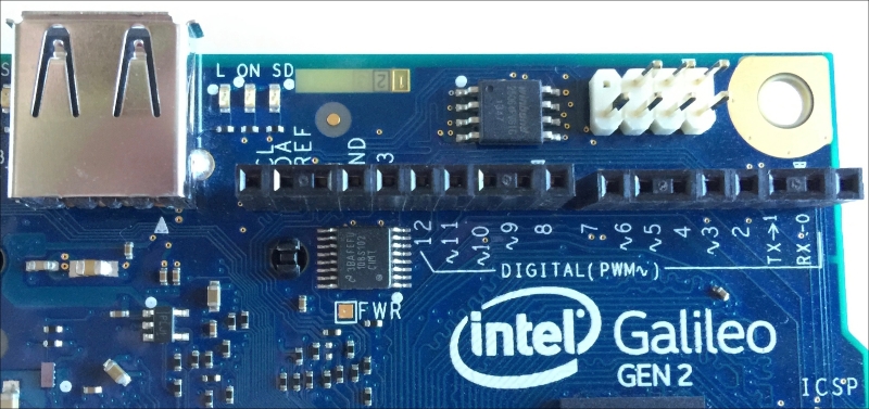
As it happens in the Arduino Uno R3, we can use six of these digital I/O pins as PWM (Pulse Width Modulation) output pins. Specifically, the pins labeled with a tilde symbol (~) as a prefix to the number have this capability: pins ~11, ~10, ~9, ~6, ~5 and ~3. The following are the pins that compose the header from left to right:
SCL
SDA
AREF
GND
13
12
~11
~10
~9
8
7
~6
~5
4
~3
2
TX->1
RX<-0
The next image shows the 14 digital I/O pins and the six PWM output pins labeled with a tilde symbol (~) as a prefix for the number. The first two pins, starting from the left are for the two I2C bus lines: SCL (Serial CLock) and SDA (Serial DAta). The last two pins, starting from the left, labeled TX->1 and RX<-0 are the UART 0 port pins. A UART port stands for Universal Asynchronous Receiver/Transmitter.
The six analogous input pins numbered from A0 to A5 are located in the lower-right corner of the board, as in the Arduino Uno R3. On the left-hand side of the analog input pins, we can see the following power pins that compose the power header:
POWER
IOREF
RESET
3.3V
5V
GND
GND
VIN
The VIN pin in the power header provides the input voltage that is supplied to the board through its power jack. The power supply included in the box provides 12V. However, the board can operate with an input voltage ranging from 7V to 15V. The board also provides support to Power over Ethernet, also known as PoE, this passes the electrical power to the board along with data on the Ethernet cable.
The following screenshot shows the power pins, also known as power headers, and the six analog input pins:

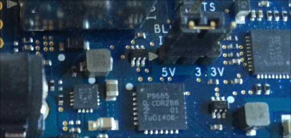
The board includes a jumper labeled IOREF that allows us to select between a 3.3V or 5V shield operation and provides voltage-level translation to all the I/O pins. Based on the jumper position, the board can work with either a 3.3V or 5V Arduino shield. By default, the IOREF jumper is set to the 5V position, and therefore, the initial setting allows us to work with 5V shields. The following screenshot shows the IOREF jumper set to the 5V position.
Tip
The IOREF pin in the power header provides the operational voltage reference based on the IOREF jumper position. Thus, based on the IOREF jumper position, the voltage reference in the IOREF pin can be either 5V or 3.3V.
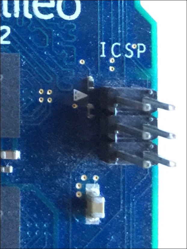
On the right-hand side of the board, there is a 6 pin, specifically 2x3 pin, ICSP (In-Circuit Serial Programming) header, labeled ICSP. The location of this header is also compatible with the Arduino 1.0 pinout. The following screenshot shows the ICSP header: