
Constructive Solid Geometry (CSG) is a modeling technique that combines primitive solids with Boolean operations to create more complex shapes. FreeCAD's CSG tools are found on the Part workbench.
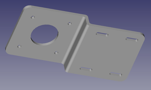
This recipe will use the Part workbench to model a simple part—an offset mounting bracket for a NEMA 17 stepping motor.
Create a new empty document and orient the view to the top using the Set to top view top-view icon or by pressing the number 2. Use the Workbench Changer to switch to the Part workbench.
Model the bent metal plate by adding and positioning three box solids. Add the first box to the drawing, and select its node in the project tree. Switch to the Data tab and edit the properties to make it 2.5 x 50 x 50 mm (height, length, width).
Create a second box with the same dimensions but edit the placement to move the box 50 mm in the X direction and 10 mm in the Z direction. This will place the second cube next to the first and shifted upward.
Add a third cube to connect them. Make its dimensions 10 x 2.5 x 50 mm and shift its placement 50 mm in the X direction.
If you rotate your view slightly, your three solids should look like the following figure:

Next we'll create the slots. FreeCAD doesn't have a slot feature so we'll make a solid in the shape of the hole we want. Later, we'll subtract it from the plate to create the hole.
Add another box and set its dimensions to 10 x 10 x 3 mm.
We want the slot to have rounded ends so we will fillet the box. Select the box and press the menu Part | Fillet.
The combo view will switch to the Tasks panel and show the fillet options. You can use this to refine your edge selection and set the radius of the fillet. For our example, select Edge1, Edge3, Edge5, and Edge7. We used a value of 1 for the radius. Clicking on the OK button will apply the change. If you make a mistake, double-click the fillet object in the tree to change the properties and try again.
Once the cube looks right, select it and duplicate it with the menu item Edit | Duplicate selection. Repeat this twice more so that we have a total of four fillet objects. Select each one and change its placement properties to move it into position on the raised part of the plate. The position is up to you. Just make sure the fillet objects completely penetrate the plate.
Now add five cylinders for the holes. Change their placement and radius properties. The center hole is 22.5 mm and the small screw holes are 2.5 mm.
With all the solids added to the project, it should like the following image:

We're almost ready to subtract the cylinders and slots from our base plate, but we first need to clean things up a bit. In the project tree, select all of the cylinders and fillet objects. With all of them selected, click on the Make a union of several shapes icon:

Now select the three boxes for our base plate and repeat the operation, fusing them into a single object.
You should now have two fusion objects in the tree, one for the base plate and one for the holes that will be cut from it. First select the base plate fusion, and then with Ctrl held down, select the other. Click on the Make a cut of two shapes icon:

The order in which you select the objects is important. The first object will be cut by the second. If all goes well, you will have an object that looks almost like the image at the beginning of the recipe.
To finish it off, we've applied another round of fillets to the corners of the plate and to the corners of the bend. The complete object should look like the image at the beginning of this recipe.
Union operations add objects together. The solids don't have to be touching or overlapping. After a union, they will have a single location and orientation.
A difference Boolean cuts the first object with the second. If the two objects don't overlap, the original object will be unaffected.
An intersection eliminates everything except the area where the original two objects overlapped.
After any of these operations, a new object is created and the original items become its hidden children. You can delete the parent node and toggle the original object visible to get back to where you were. Objects such as fillet and chamfer can be double-clicked to reopen the dialog that created them and adjust the options.