
This, of course, leads us nicely onto the subject of creating believable materials for our models. Because this is just a quick start exercise and we will be devoting an entire chapter to the development of some very specific materials in V-Ray, we will deal with just two things here. First, we will demonstrate how to apply existing materials to various geometry elements in the scene. And second, we will walk through the creation of a new floor material just to get a feel of how the V-Ray standard material works.
To get started, we can either continue with our current file or open up the Ch01_04_Materials.skp file from the downloadable Exercise_Files folder. This file essentially picks up where our lighting tweaks have left off. Let's introduce ourselves straight away to the V-Ray material editor by going back to the V-Ray toolbar and clicking on the M (for material editor) button. This, of course, will open up the editor window for us.
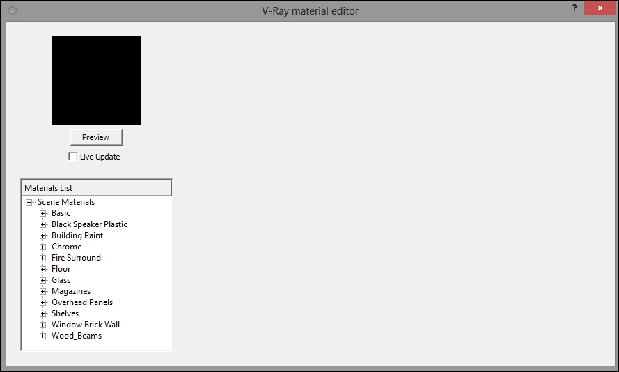
Looking in the Materials List section, you can see that we have a material named Basic. This is the plain grey material currently assigned to all the geometry in the scene. As we want to alter this arrangement, we need to briefly cover the setup or current state of geometry in the scene.
What I am referring to is the fact that everything in our scene at this moment in time has been turned into either a group or a nested group. This, for those who may be unfamiliar with SketchUp, will affect how we go about applying materials to the geometry. For instance, with one of the shelf objects selected, I can right-click on Shelves material in the Materials List section and choose the Apply Material to Selection option.
The selected material is then applied to that geometry. However, if I select a geometry group such as the main building itself, those same steps will no longer work and the material application would fail.
To apply a material to this type of geometry, we need to perform the following steps:
Double-click on the main building geometry to open up the group.
In the Edit menu, use the Select All command.
Right-click on a material in Materials List, such as Building Paint, and then choose the Apply Material to Selection option.
We need to follow a similar process when working with nested groups. Applying a material directly to a nested group such as our table won't work. However, we can perform the following steps to attain the desired result:
Double-click to open the nested hierarchy.
Left-click to select one of the groups.
Select a material from the Materials List section.
Right-click and choose Apply Material to Selection.
The material should then apply just fine. If it doesn't, we will need to perform the following extra steps inside the nested group:
Double-click on one of the nested groups.
Use the Select All command from the Edit menu.
Select a material from the Materials List section.
Right-click and choose Apply Material to Selection.
This may seem like a clunky way to get things done, especially if we are coming to SketchUp from other 3D applications. However, once the process becomes familiar to us, it really does become second nature and flows quite freely.
Now that we understand the process of applying materials, go ahead and see if you can get the named textures in Materials List applied to their related scene objects. This is a good way to get some practice at working with the preceding outlined steps.
To keep ourselves moving forward, let's run through the creation of a material of our own. This is what we will use to texture the floor in our scene.
Tip
Do keep in mind that we already have a Floor Material in our Materials List that can be used as a reference at any point if you should get a little stuck.
To move forward, we can either continue with our current file or open the Ch01_05_FloorMat.skp file from our Exercise_Files folder.
The first thing we want to do here is create a new V-Ray standard material for ourselves. So, let's perform the following steps in Materials List:
Right-click on either the Scene Materials label itself, or with the Scene Materials label selected, right-click on an empty area of the Material List panel.
In the pop-up menu, hover over the Create Material option and select the Standard material from the flyout.
Then, we need to locate the newly created label named DefaultMaterial in the Materials List.
Right-click on it and choose the Rename Material option from the pop up.
In the Rename Material window that opens up, call the new material My Floor and click on OK.
Of course, we will want to assign this material to the floor geometry straight away. Our new material is currently using grey for its diffuse color, making it the same as the already assigned basic material; we will avoid any potential confusion by changing our new material's diffuse color to something that will enable us to tell them apart.
To change this to something more recognizable, let us perform the following steps:
In the Diffuse rollout of our My Floor material, click on the diffuse color swatch.
In the Select Color dialog box, choose a color that would be very noticeable in the scene, such as the burnt orange I will create here. Let's use the HSV settings of HSV 12, 240, and 218.
Then, enable the select tool from the Large Toolset toolbar.
Triple-click on the floor geometry in the scene to ensure that it is all selected, or we could double-click and then use the Select All command from the Edit menu.
Right-click on the My Floor material name in the editor and choose Apply Material to Selection from the pop up.
If our burnt orange color appears in the viewport, we know that we have successfully applied this new material to the geometry; not that we will leave it set at burnt orange of course. In fact, we won't actually use the diffuse color swatch at all. Instead, we will make use of a number of bitmap or image files to help give our floor material a little more visual interest. To do this, perform the following steps:
Click on the map button (m) to the right of the diffuse color swatch.
From the drop-down list that appears under the Preview button, select the TexBitmap option.
In the Open Bitmap File dialogue box that appears, navigate to your downloaded
Exercise_Filesfolder, and from theTexturessubfolder, click to open theFloor.bmpfile.
Then, click on OK to close the texture editor window.
And finally, let's lower the diffuse map's overall level of contribution by setting the spinner value to 0.25.
We should now see our bitmap texture appear in the SketchUp viewport. At this moment, however, the default UV mapping coordinates are causing the bitmap to tile way too much for my liking. To rectify this, we need to use the controls found in SketchUp's own Materials editor.
To access that, let's perform the following steps:
Click on the Paint Bucket tool over on the SketchUp toolbar.
In the SketchUp Materials editor window, click on the Edit tab.
In the Edit tab, we have width and height controls that appear just below the image naming field. Click on the Lock/Unlock aspect ratio button that appears next to these fields.
Enter values of
3.00meters for the width and2.30meters for the height.Close the SketchUp Materials editor.

We should be able to see the difference this has made straight away in the viewport.
Next, we need to apply some parameter changes that will help us add some realism to our floor material. The first thing that we need are some reflections. To do this, we need to specifically add reflection controls to our V-Ray standard material.
Note
Although V-Ray Version 2.0 in SketchUp, just like other applications such as 3ds Max and Maya, now has a V-Ray Material that has all of the relevant parameter sections such as reflection and refraction set up and ready to work, there are some drawbacks to it that we will discuss in later chapters that preclude our use of it in this instance.
In the V-Ray material editor, let's perform the following steps:
Right-click on the My Floor material.
In the pop-up menu, hover over the Create Layer option, and from that flyout, choose the Reflection option.
Next, in the General area of the Reflection rollout, set the spinner next to the reflection color swatch to a value of 0.25. (We can double-click and type the values in any of these fields if we want.)
Then, we need to click on the map button (m) next to the reflection color swatch. In the texture editor parameters window that appears, click on the map button (m) for the Perpendicular controls.

In the drop-down list below the Preview button, choose the TextBitmap option.
And, in the Open Bitmap File dialog box that appears, navigate to
Exercise_Files|Texturesand once more choose theFloor.bmpfile.Finally, click on OK in the two open dialogs to go back to the materials editor window.
Placing the bitmap in the perpendicular channel here will give us some nice variation in the reflection intensity, which will automatically make things feel a little more natural. Next, we need to add some breakup to those reflections. So, in the Reflection rollout of the My Floor material, go to the Glossiness section and set the Hilight and Reflect values to 0.85.
Then, as a finishing touch, we can add a bit of a textured feel to the floor along with extra breakup by adding a subtle bump map to the material. To do that, let's perform the following steps:
Open up the Maps rollout at the bottom of the material controls.
Put a check in the Bump option, and at the same time, set its spinner value to 0.1.
To add a map for the bump effect, click on the map button and select the TextBitmap option from the drop-down list beneath the Preview button.
In the Open Bitmap File window that appears, navigate to
Exercise_Files|Texturesand choose theWall_Stucco_Bump.bmpfile.In the UVW section at the bottom of the texture editor controls, set u and v Repeat values to 4 and then click on Ok to exit the editor.
We can now take a render and see how things are looking by coming up to the V-Ray toolbar and clicking on the render button. Hopefully, what you have should look just like the following render:
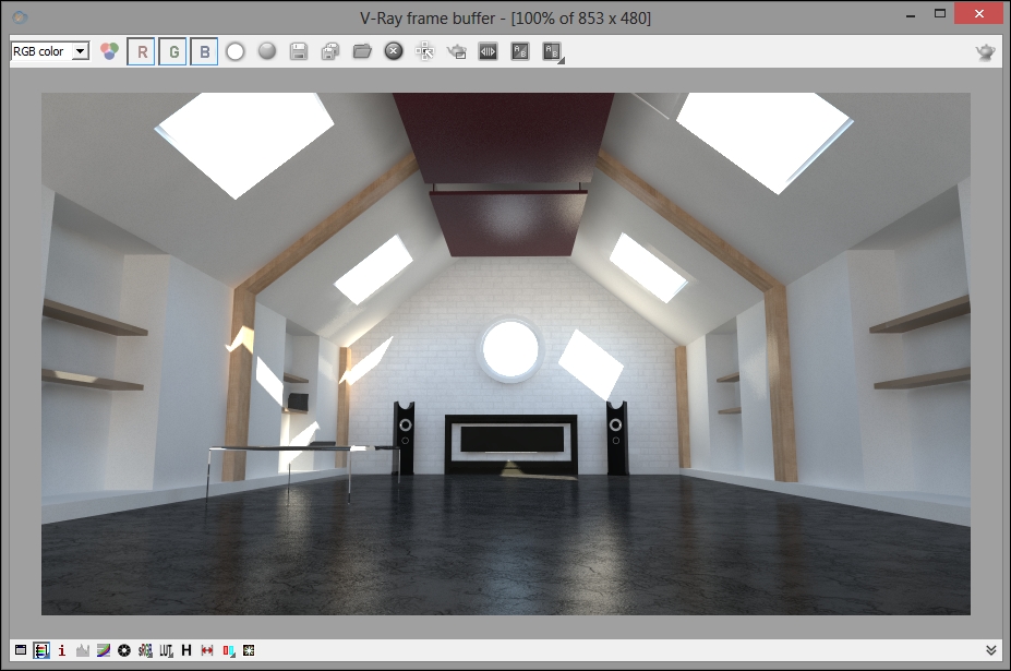
We are closing in on a decent quick start image here. However, before we go ahead and create our final output render settings, let's just see how we can tweak things a little, now that all of our materials are fixed in place.
One area that I will want to address are the super bright whites that we are currently getting inside the render. You can find these by right-clicking on the image inside the V-Ray frame buffer, which should pop up a Pixel information dialog that contains RGB data readouts for varying image bit depths.
Note
V-Ray can do this because, by default, renders inside the frame buffer are stored at the highest bit depth possible using floating point values.
The one we are specifically interested in would be the Color (float) option. Whenever all three numbers in this readout go above the value of 1, which is pure white in floating point terms, then we know that what we are looking at is one or more super bright pixels in the image.
Sometimes, we can use these to good effect in our renders, especially when it comes to using the new Lens Effects feature of V-Ray Version 2.0. At other times, however, the burnout these super bright pixels cause, particularly in areas where direct light falls on an already bright texture such as our white walls, can be extremely undesirable. This means that it will always be useful to know which V-Ray tools can be used to help deal with this. One set of such tools would be the color mapping controls.
However, before we go ahead and make any changes, I am going to open up the Ch01_06_Tweaks.skp file from the Exercise_Files folder, which again picks up from where we currently have the scene. (Again, feel free to continue on using the current file, if you prefer.)
To deal with our super brights, let's perform the following steps:
Reopen the option editor by using the button on the V-Ray Main toolbar.
Inside the dialog, we want to open up the Color Mapping rollout and select the Exponential option from the Type drop down.
We also need to set Bright Multiplier here to a value of 1.0 instead of the default 0.8.
This simple change in the color mapping type will prevent any of the RGB values in our image from climbing above a value of 1. Another effect of this color mapping change is that our rendered image will become a little less bright and the RGB values of our extremely blown-out sky will drop to levels below 1, meaning that we can now see a little bit of blue in there!
Another lighting tweak we might want to make at this point is in connection with the current positioning of the direct sunlight in our view. At this moment in time, the sunlight coming through the skylights is creating one or two bright spots on the left side wall, which are looking a little messy and may need cleaning. We can do that by basically shifting the Sun a little in our scene. To do that, we need to perform the following steps:
Open up SketchUp's Shadows control dialog from the Window menu.
Then, set the time of day to 11.10 a.m. by using either the spinner or clicking in the text field and typing.
With that done, we will not only eliminate those distracting highlights, but we will actually create another element of symmetry in the shot in which the spots of light now fall on either side of the window opening.
One element that seems to be a little bit lacking in the scene would be occlusion or contact shadows. We may particularly expect to see these in corner areas of the room, especially the shelving recesses. At this point, we ideally want to add them without creating an extra image element that would need to be composited in another application. In this instance, we will choose the easiest route available to accomplish this and enable V-Ray's ambient occlusion option by following the given steps:
With the V-Ray Options dialog open, go to the Indirect Illumination rollout.
In the Ambient Occlusion section, check the On box.
Set the radius amount to 8.5.
As we want the effect to be fairly subtle, let's set Amount to 0.35.
With our lighting tweaks in place, a final, slightly distracting element that we may want to tackle could be the material we have applied to the shelves in the scene. I am not entirely convinced that what we have created sits well in the scene. So, I would like to experiment a little and try applying the same material that we are using for our overhead panels.
To do that, follow the given steps:
Select all of the shelf objects in the scene.
Open up V-Ray material Editor.
Right-click on the Overhead Panel material.
From the pop up, choose the Apply Material to Selection option.