
We can apply thickness to most linear 2D entities and also create linear 3D entities like 3D polylines and splines.
Almost all linear entities that we know from 2D have a property called Thickness, whose value represents a height along the Z axis (a better word actually should be height). This is the only 3D feature available in AutoCAD LT and can be applied to text (if made with a text style that uses an SHX font), but beyond that is quite limited.
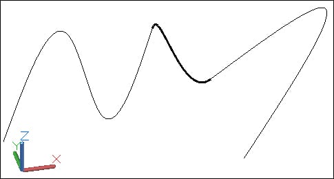
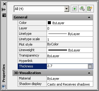
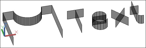
The best way to change the value of thickness is with the PROPERTIES command, Ctrl + 1. A line is still a line or a text still text, but with a proper visualization, these entities can transmit a 3D feeling:
Polylines created with the PLINE command are 2D, not allowing for vertices with different Z coordinates. These polylines are designed by lightweight polylines. But what if a single object is needed to be composed by segments whose endpoints have different Z coordinates?
The answer is to create 3D polylines. Three processes are available:
3DPOLY: This command (alias3P) creates 3D polylines from the start. It works like theLINEcommand, but the result is a single object.JOIN: This command (aliasJ) creates 3D polylines from a contiguous sequence of lines with shared endpoints. It is enough that one endpoint of a line is out of the plane for a 3D polyline to be created.PEDIT: The same command (aliasPE) used for the creation of 2D polylines from lines and arcs can also be applied to join lines to a 3D polyline. The first object must already be a 3D polyline.
Note
Starting with version 2012, the best way to apply the JOIN command is to select all the line segments at the first command prompt, without specifying a source object. Depending on the type of selected objects and their positions, the most suitable object is automatically created.
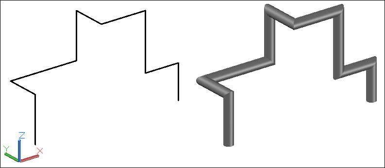
And in what situations may we have utility for 3D polylines?
3D polylines are particularly useful to measure objects that develop in different directions, such as piping or wiring, and to define paths for other 3D objects such as piping. The creation of 3D solids and surfaces from linear objects is the subject of Chapter 4, Creating Solids and Surfaces from 2D.
Splines are smooth linear objects, normally without corners that pass through or near specified points. Spline is short for Nonuniform Rational B-Spline (NURBS). Splines are described by a set of parametric mathematical equations, but have no fear, for AutoCAD will internally deal with this, we will not have to!
Splines are used whenever we need smooth curves and are also the foundation for NURBS surfaces, the most used surfaces in the automotive or aeronautic projects.
To create a spline we apply the (guess?) SPLINE command (alias SPL). By default, the command only prompts for the location of fit points, and the spline passes through the specified points. An Enter finishes the spline and the Close option creates a closed spline.
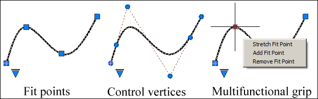
We can control splines by two sets of vertices:
Fit points: These are the points used to create the splineControl vertices: These are the points that define the spline
When selected, the
small blue triangle allows switching between Fit points and Control vertices. To edit a spline is very simple: we select it, without command, and work with grips. We can either click a grip and move it, or we can place the cursor over a grip and on the grip menu choose to move the vertex, add one, or remove that vertex. This last process is known as multifunctional grip.
Note
Since AutoCAD 2012, the JOIN command is also a great tool for the creation of complex splines. We may have a contiguous and non-planar sequence of lines, arcs, elliptical arcs, splines that the result is a single spline.
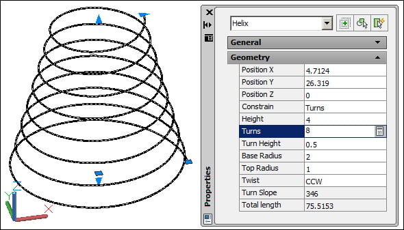
With the HELIX command we can create 2D or 3D helixes or spirals. By default, the command prompts for the center point of the base, base radius, top radius, and height. As options, we have the position of the axis endpoint, the number of turns, the height of one complete turn, and the twist (if the helix is drawn in the clockwise or the counterclockwise direction). To edit a helix object, we can use grips or the PROPERTIES command.
If we explode a helix object,
the result is a spline. The BLEND command, new in Version 2012, creates a special spline that connects two open linear objects. The command only prompts for the selection of the first curve and the selection of the second curve. Selections must be near the endpoints to connect. The Continuity option allows for the choice of the applied type of continuity: Tangent with a tangency continuity (known as G1 continuity), or Smooth with a curvature continuity (known as G2).