Book Image

Autodesk AutoCAD 2013 Practical 3D Drafting and Design

By : JOAO ANTONIO C DOS SANTOS
Book Image

Autodesk AutoCAD 2013 Practical 3D Drafting and Design

By: JOAO ANTONIO C DOS SANTOS

Overview of this book

AutoCAD is a computer-aided design (CAD) and drafting software application. AutoCAD supports both 2D and 3D formats. AutoCAD is used in a range of industries and is utilized by architects, project managers, and engineers, among others."Autodesk AutoCAD 2013 Practical 3D Drafting and Design" will take you beyond the 2D frontier and help you create accurate 3D models that simulate reality. This book is crammed full of creative and practical tutorials which will help you master the third dimension. From exercises on coordinate systems to creating solids and surfaces from 2D, you will wonder how you ever designed without this resource by your side."Autodesk AutoCAD 2013 Practical 3D Drafting and Design" is full of hands-on studies and projects that will help develop your 3D skills. Starting from the assumption of only a very basic knowledge of AutoCAD, this book will help you master 3D visualization and coordinate systems, create 3D models from 2D drawings, and from basic shapes, measure volumes, and other information, obtain 2D construction drawings from 3D models as well as how to apply lights and materials to get photorealistic images.
Table of Contents (20 chapters)
Autodesk AutoCAD 2013 Practical 3D Drafting and Design
Credits
About the Author
About the Reviewers
www.PacktPub.com
Preface
Index

Creating solids and surfaces with different sections


Sometimes, we need to create some non-regularly shaped elements. The next command represents an easy way, and is also applied for the creation of terrains, curtains, and so on.

The LOFT command

The LOFT command (no alias) creates a solid or surface from the selection of two or more cross sections. If all sections are closed, the result is solid, unless the MOde option is set to Surface.

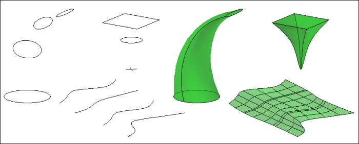
The command shows the same information as in previous commands. It then asks for the objects that define the cross sections in the correct order. As sections are being selected, the lofted object is being previewed. When ending the selection, we press the Enter key. The command informs us of the number of sections selected and continues:

Command: LOFT
Current wire frame density:  ISOLINES=4, Closed profiles creation mode = Solid
Select cross sections in lofting order or [POint/Join multiple edges/MOde]: Selection
n cross sections selected

After selecting all...