
To obtain both bumps and displacement effect in Cycles, there are a few options.
The simplest way to have bumps on our material's surface is by connecting the Color or the Fac output of a texture node to the Displacement input socket of the Material Output node. Despite the fact that the socket's name is Displacement, the effect I'm writing at the moment is just a simple bump effect (by the way, a very good one), affecting as a whole the total result of the sum of the material's nodes.
Just as we did for color textures, the bump textures can also be mapped on the object with the Mapping and Texture Coordinate nodes. There is naturally also a way to set the amount (the strength) of bumpiness of the texture on the object's surface:
Open the
start_02.blendfile and set the 3D view to the Rendered mode.Put the mouse pointer in the Node Editor window and press Shift + A to bring up the Add menu and select a Math node from the Convertor item (press Shift + A and go to Convertor | Math).
Connect the Fac output of the Wave Texture node, already connected to the Roughness input socket of the Glossy BSDF shader node, to the first upper gray Value input socket of the Math node. Connect the Math node output to the Displacement input socket of the Material Output node.
Set the operation mode of the Math node to Multiply. By sliding the second Math node Value, we can set the influence, the strength, of the bumping. Try, for example, to set it to 3.000, as shown in the following screenshot:

Save the file as
start_14.blend.
Put simply, the gray-scale values of the texture are multiplied for the value we put in the second slider of the Math node. For example, if we set a value of 0.500, the intensity of the effect will be the half of the default one (1.000 x 0.500 = 0.500). With a value of 3.000, the effect will be three times the default one. Similar to Blender Internal, the value can also be set as negative (-3.000 in this case), thereby inverting the direction of the bump effect.
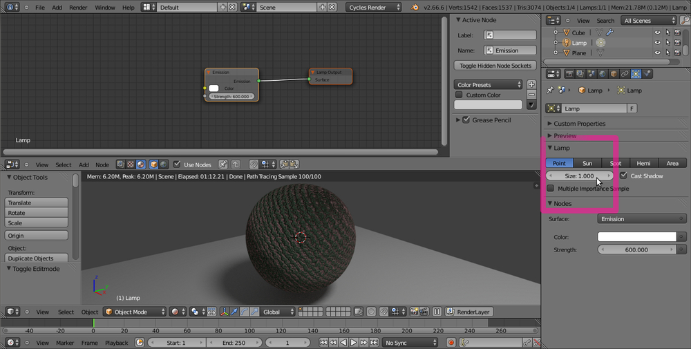
Note that there is an evident problem at the terminator of the spheroid (that is, at the limit of the lit surface with the self-shadowed one) that seems as a general limit of path tracers. To get rid of it, you can try to subdivide the mesh by a higher value (a little impractical method, honestly), but this not always is enough. A different way is to modify the Size value of the lamp (or the scale if you are using a mesh-light). Select the lamp in the Outliner, and in the Size button under the Type of Lamp row in the Object Data window, set Size to 1.000. The terminator looks a lot smoother now (along with also, obviously, the projected shadow on the plane):
From Blender 2.65 onwards, a Normal input socket has been added to all the appropriate shader nodes, to input values for the bump of each shader node itself. This input socket must be fed by a Bump node (press Shift + A and go to Vector | Bump). This is how we do so:
Starting from the
start_14.blendfile, select the Math node in the Node Editor window and delete it (press X).Put the mouse pointer in the Node Editor window and press Shift + A to add a Bump node (press Shift + A and go to Vector | Bump).
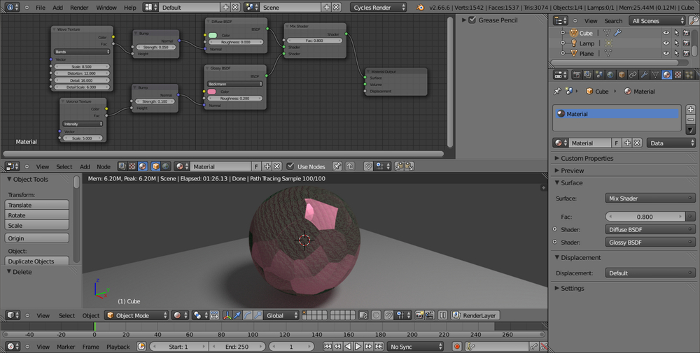
Connect the Fac output of the Wave Texture node to the Height input socket of the Bump node and the output of the latter to the Normal input socket of the Diffuse BSDF shader node. Set the Strength value to
0.050.Add a Voronoi Texture node (press Shift + A and go to Texture | Voronoi Texture) and a new Bump node (press Shift + A and go to Vector | Bump). Connect the Fac output of the Voronoi Texture node to the Height socket of the new Bump node and connect the latter to the Normal input socket of the Glossy BSDF shader node:

Save the file as
start_15.blend.
As you can see in the preceding image, it's now also possible to have the bump effect per node. That is, every shader node can have a different bump with different strength (note that it's no more needed to connect anything to the Displacement input socket of the Material Output node). This way, we can have a certain bump effect only on an established component of the shader (the diffuse shader), and a different bump on the other components (the glossy shader), as shown here:
As far as displacement is concerned, we can use the Displace Modifier option in the Object Modifiers panel, using a texture to be set in the Textures tab under the Properties panel. It seems no Cycles texture can be used for this at the moment, but only the old Blender Internal textures at disposal from a menu. In this case, the displacement is not behaving any differently from the displacement we have in BI. The mesh must be subdivided (usually the Subdivision Surface modifier is used, but also the Multiresolution modifier can be used) and then displaced. In short, there is nothing as a "micro-polygon displacement rendering" yet.
By the way, by enabling Experimental in the Feature Set tab under Render in the Render window, it's possible to have access to a (still incomplete) displacement feature:
Go to the Render window under the Properties panel. In the Render tab click on the Feature Set button, by default labeled with Supported, and select Experimental.
Go to the Object Data window to find a new tab named Displacement, where we can choose between three options: Bump, True, or Both (the Use Subdivision and Dicing Rate buttons don't seem to work yet).
Note
Bump will give us the average bump effect, which is the same as connecting the texture output in the Displacement input of the Material Output node (that we'll have to do in any case).
By setting the method to True, we can have a displacement effect not different from the Displace Modifier output, and the mesh must be subdivided.
Both will use the texture gray-scale values' information for a displacement and the bump effect together.
Select True.
Reselect the spheroid. Go in the Material window under the Properties panel, and in the Displacement tab click on the blue Value button labeled Wave Texture to select an Image Texture node from the pop-up menu.
Click on the Open button, browse to the
texturesfolder, and load thequads.pngimage.Just under the Open button, click on the Color Space button to set it to Non-Color Data.
Split the bottom 3D window to open a UV/Image Editor window. Press Tab to go in edit mode and then press U with the mouse pointer in the 3D window. In the UV Mapping menu, select Smart UV Project, then press Tab again to go out of edit mode (this is a quicker way of unwrapping the spheroid which, remember, at its lower level of subdivision is still a cube. If you want, you can do a better unwrapping by placing seams to unfold it and by selecting a normal Unwrap from the menu).
Go to the Object Modifiers window and raise the Subdivisions levels for both View and Render to
6:
In any case, this is just for a temporary demonstration, the feature is still incomplete and at the moment seems to work (quite) properly only if the texture is mapped with UV coordinates. This is definitely going to change in the future.