Overview of this book
The Raspberry Pi is a powerful low-cost credit-card-sized computer, which lends itself perfectly as the controller for a sophisticated home security system. Using the on-board interfaces available, the Raspberry Pi can be expanded to allow the connection of a virtually infinite number of security sensors and devices. The Raspberry Pi has the processing power and interfaces available to build a sophisticated home security system but at a fraction of the cost of commercially available systems.
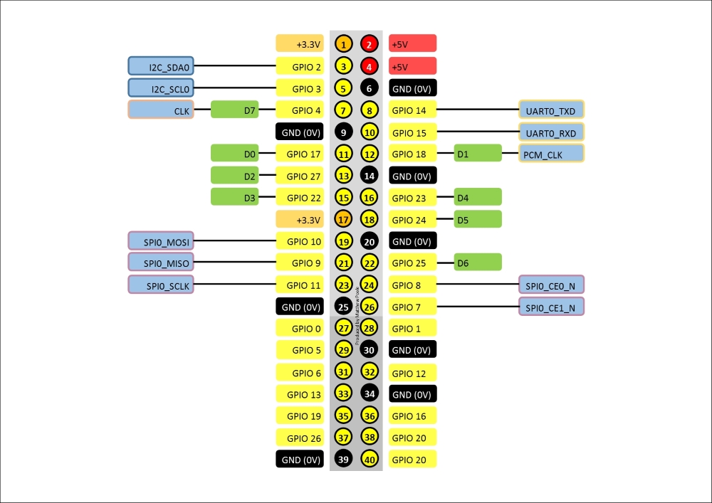
Building a Home Security System with Raspberry Pi starts off by showing you the Raspberry Pi and how to set up the Linux-based operating system. It then guides you through connecting switch sensors and LEDs to the native GPIO connector safely, and how to access them using simple Bash scripts. As you dive further in, you’ll learn how to build an input/output expansion board using the I2C interface and power supply, allowing the connection of the large number of sensors needed for a typical home security setup.
In the later chapters of the book, we'll look at more sophisticated topics such as adding cameras, remotely accessing the system using your mobile phone, receiving intrusion alerts and images by e-mail, and more.
By the end of the book, you will be well-versed with the use of Raspberry Pi to power a home-based security system that sends message alerts whenever it is triggered and will be able to build a truly sophisticated and modular home security system. You will also gain a good understanding of Raspberry Pi's ecosystem and be able to write the functions required for a security system.