

Here is a brief introduction of the developer kits we will use into this book.
The first kit is the BeagleBone Black, which is a low-cost, community-supported development platform for developers and hobbyists. It's able to boot Linux in under 10 seconds and get started on development in few minutes with just a single USB cable. This board is widely used on several prototypes on the Internet, so it's a board that every embedded programmer should know.
The second kit is SAMA5D3 Xplained , which is a fast prototyping and evaluation platform that comes with a rich set of ready-to-use connectivity, storage peripherals, and expansion headers for easy customization. A USB device connector can be used to power the board as well as for programming and debugging it. This board is very interesting due the fact it uses a very low power-consuming CPU with good performances and with a lot of industrial-oriented peripherals.
The last (but not least) kit is Wandboard, which is a complete computer with high-performance multimedia capabilities, a good peripheral equipment and, in contrast with the other boards, it's composed by a core module and an easy interface board to customize or modify. The board is very interesting because it can be equipped with a multicore CPU and because it comes as a CPU module connected to a carrier board, which allows embedded developers to have a highly hardware-customizable device.
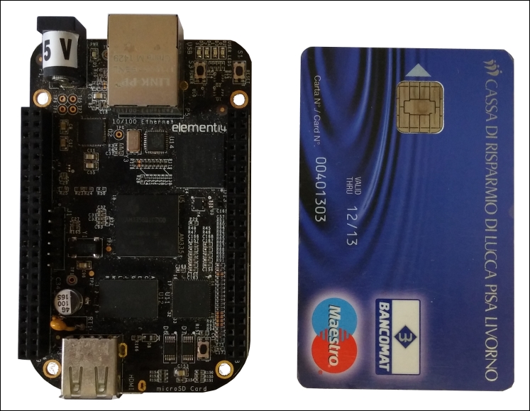
In the following image, there is a picture of the BeagleBone Black, with a credit card, so that you can have an idea about the real dimensions of the whole system:
Here are some interesting URLs where you can read some useful information regarding BeagleBone Black:
The main hardware key features of my BeagleBone Black (revision C) are reported in the following table:
|
Part |
Specification |
|
Main processor |
ARM processor: Cortex-A8 @ 1Ghz |
|
Graphic processor |
PowerVR SGX |
|
SDRAM memory |
512MB DDR3 |
|
On-board flash |
4GB, 8-bit eMMC |
|
USB 2.0 ports |
1 device
1 host
|
|
Serial port |
UART0 via 6 pin 3.3 V TTL connector |
|
Ethernet |
1 port 10/100 via RJ45 connector |
|
SD/MMC |
1 slot microSD |
|
Video/audio out |
Micro HDMI |
|
Buttons |
1 for power
1 for reset
1 user controllable
|
|
LED indicators |
1 for power
2 on Ethernet port
4 user controllable
|
|
On-board Wi-Fi/bluetooth |
None |
|
SATA |
None |
|
Expansion
Connectors
|
Power 5V, 3.3V, VDD ADC (1.8V)
GPIOs 3.3V
SPI, I2C, LCD, GPMC, MMC0-1, CAN
7 ADC (1.8V max)
4 timers
4 serial ports
3 PWMs
|
|
J-TAG connector |
20 pins J-TAG (not populated) |
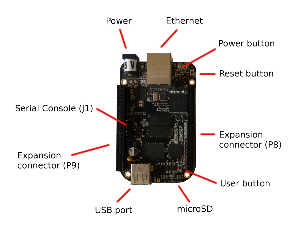
Then, the following image shows a top view of the BeagleBone Black, where we can see some interesting things:
The connector J1 used to access the serial console.
The Ethernet connector.
The power connector.
The two expansion connectors P8 and P9, where we can connect the dedicated extension boards and/or custom peripherals (these connectors will be explained in detail in the upcoming chapters).
The microSD slot.
The USB host port.
The reset button does what it says while the power button can be used to turn on/off the board, and the user button, which is user controllable, can be used to do an alternate boot on the microSD card instead of the on-board eMMC.
From the preceding image, we can see that the BeagleBone Black doesn't look like a PC, but it can act as a PC! The BeagleBone Black is a fully functional single-board computer and can be readily used as a PC if required by connecting a monitor to the HDMI port and attaching a USB keyboard and mouse through a USB hub. However, it is more suited to embedded applications, where it can act as more than a PC due its expansion connectors, and we can stack up to four expansion boards (named capes) that are useful for several purposes.
In this book, we'll see how we can manage (and reinstall) a complete Debian distribution that allows us to have a wide set of ready-to-run software packages, as a normal PC may have (in fact, the Debian ARM version is equivalent to the Debian x86 version). Then, we'll see how we can use the expansion connectors to connect to the board. Several peripherals are used to monitor/control the external environment.
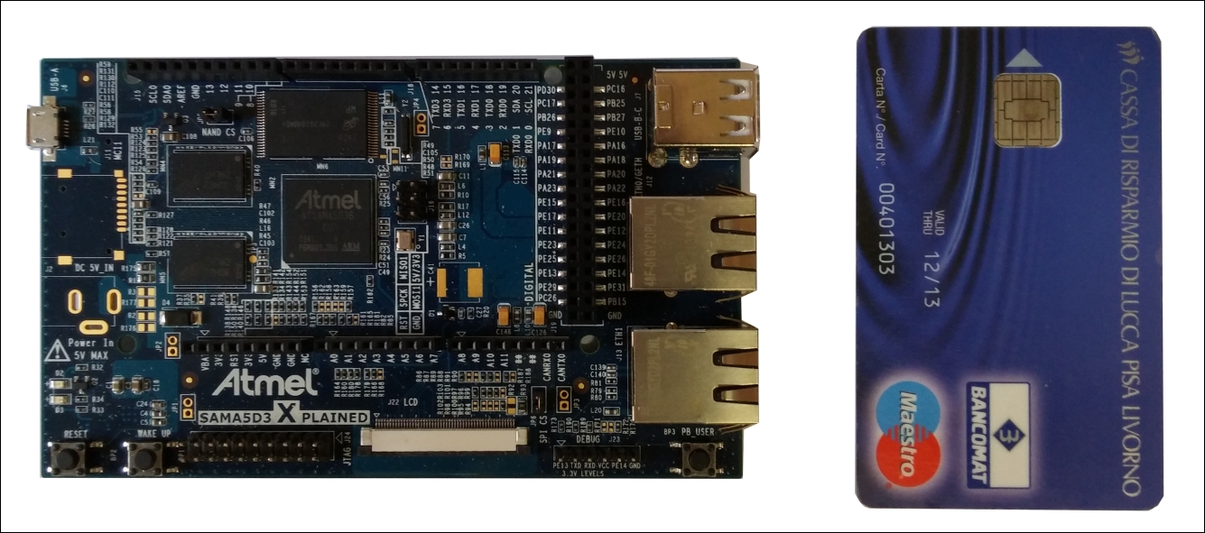
In the following image, as done earlier, there is a picture of the SAMA5D3 Xplained, with a credit card, where we can easily notice that compared to the BeagleBone Black, this board is larger. This is due the fact that we have more connectors and ports mounted on the board. In particular, the expansion connector in the center of the board is Arduino R3 compatible, so we can use its extension boards on it:
Here are some interesting URLs where you can read about SAMA5D3 Xplained:
Note that there are several versions of the SAMA5D3 Xplained board depending on the CPU version, so we can have SATSAMA5D31, SATSAMA5D33, SATSAMA5D34, SATSAMA5D35, and ATSAMA5D36. Each CPU has the same core, but a different peripheral set.
In this book, we will use ATSAMA5D36, and the main hardware key features of this version are reported in the following table:
|
Part |
Specification |
|
Main processor |
ARM processor: Cortex-A5 @ 536Mhz |
|
Graphic processor |
LCD controller with graphics accelerator |
|
SDRAM memory |
256MB DDR2 |
|
On-board flash |
256MB, NAND flash |
|
USB 2.0 ports |
1 device
2 host
|
|
Serial port |
UART0 via 6 pin 3.3 V TTL connector |
|
Ethernet |
1 port 10/100/1000 via RJ45 connector
1 port 10/100 via RJ45 connector
|
|
SD/MMC |
1 slot SD/MMCPlus 8-bit
1 slot microSD 4-bit (not soldered)
|
|
Video/audio out |
Digital interface |
|
Buttons |
1 for reset
1 for wake up
1 user controllable
|
|
LED indicators |
1 for power
2 on each Ethernet port
1 user controllable
|
|
On-board Wi-Fi/bluetooth |
Optional WiFi via SDIO expansion |
|
SATA |
None |
|
Expansion
Connectors
|
GPIOs 3.3V
SPI, I2C0-1, CAN0-1, VBAT
12 ADC (3.3V max)
2 timers
6 serial ports
2 PWMs
|
|
J-TAG connector |
20 pins J-TAG (populated) |
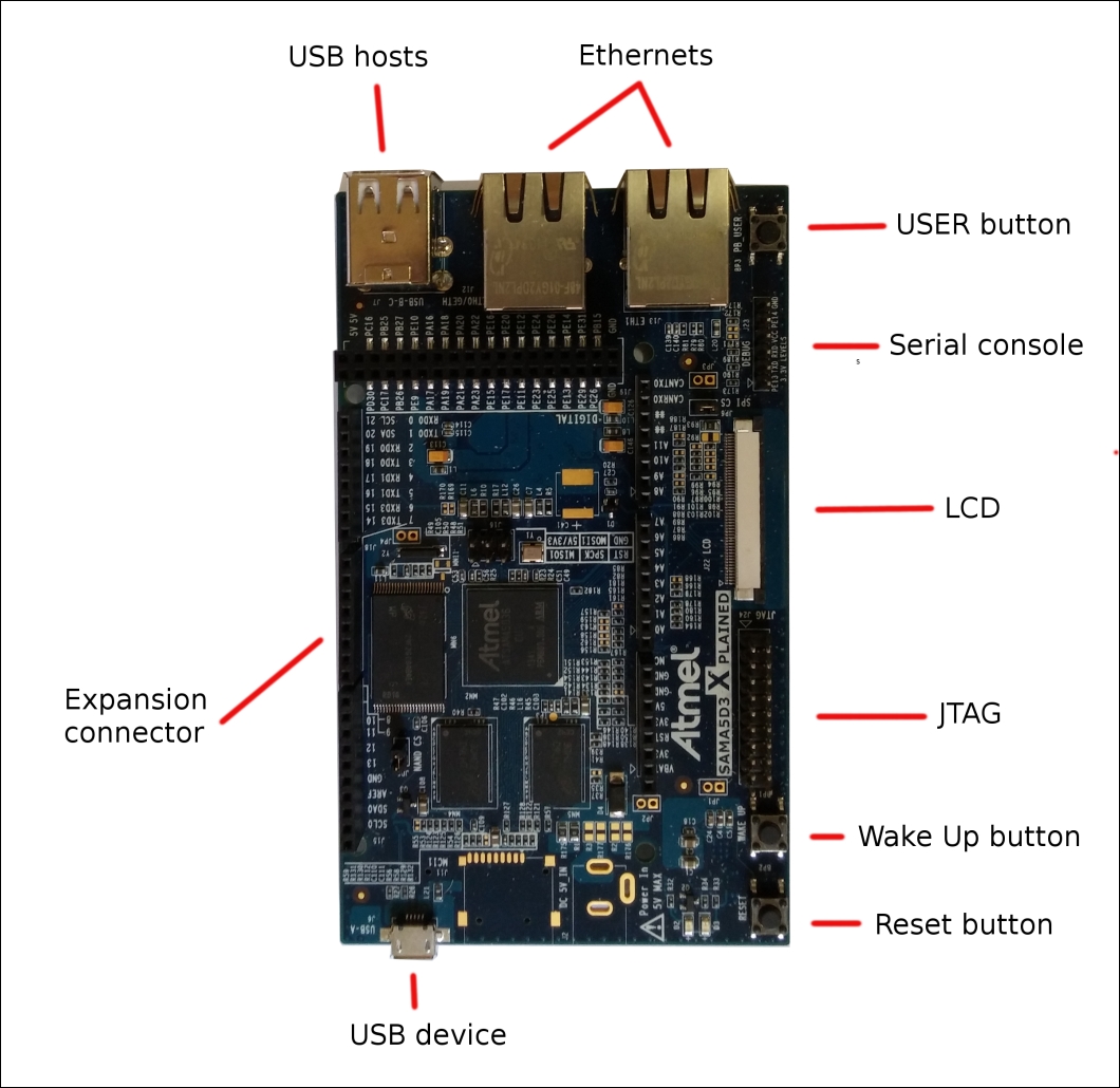
The following image shows a top view of the SAMA5D3 Xplained, where we can see some interesting things:
The connector J23 can be used to access the serial console.
The USB micro port can be used obviously as a USB device interface, but it is used also as a power supply port and as a SAM-BA USB device and USB CDC connection.
The two Ethernet connectors.
The LCD connector.
The JTAG connector.
The two USB host ports.
The expansion connector (note that these connectors are Arduino R3 compatible).
The reset button can be used to reset the board. The wake up button can be used to turn on/off the board.
This board can also act as a PC, even if it is designed for typical industrial tasks. It can resist in very hostile environment. It has low power consumption and a lot of useful peripherals for professional applications. In contrast to the BeagleBone Black, it has no HDMI connector for external monitor, but it has a dedicated connector for an LCD with touch screen.
Even for this board, we'll install a complete Debian distribution and see how we can use the expansion connectors to connect to the board.
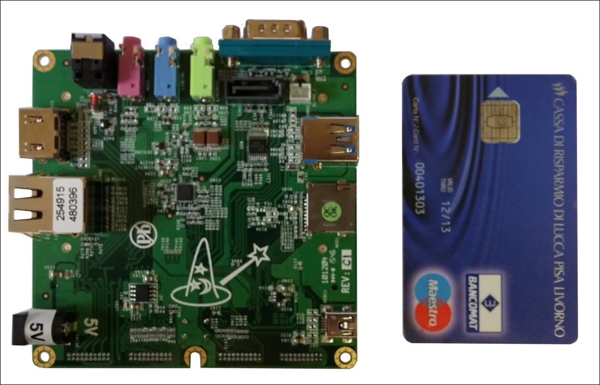
In the following image, there is a picture of the Wandboard, with the same credit card shown earlier:
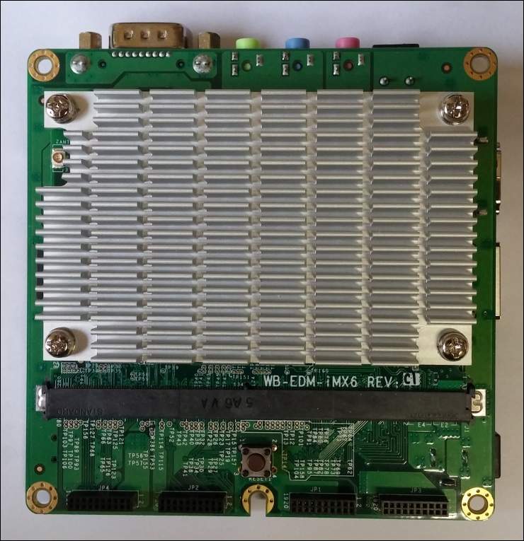
The board seems quite small, but it's actually composed of two parts: the core module is on top of the interface (or carrier) module (see the following image):
Here are some interesting URLs where you can gain some useful information regarding your Wandboard:
Note that there are several versions of the Wandboard board depending on the CPU version, so we can have the Wandboard Solo, Wandboard Dual, and Wandboard Quad. Each version has a different CPU with the same core but a different peripheral set and core numbers. In fact, the Wandboard is available as a single-, dual-, and quad-core CPU!
In this book, we will use the Wandboard Quad (revision C1), and the main hardware key features of this version are reported in the following table:
|
Part |
Specification |
|
Main processor |
ARM processor: Quad Cortex-A9 @ 1Ghz |
|
Graphic processor |
Vivante GC 2000 + Vivante GC 355 + Vivante GC 320 |
|
SDRAM memory |
2GB DDR3 |
|
On-board flash |
None |
|
USB 2.0 ports |
1 OTG
2 host
|
|
Serial port |
UART0 via standard RS232 pin9 connector |
|
Ethernet |
1 port 10/100/1000 via RJ45 connector |
|
SD/MMC |
2 slot SD/MMCPlus 8-bit |
|
Video/audio out |
HDMI
Analog audio plus optical S/P DIF
Digital camera connector
|
|
Buttons |
1 for reset |
|
LED indicators |
1 for power
2 on Ethernet port
|
|
On-board Wi-Fi/bluetooth |
802.11n/4.0 |
|
SATA |
1 connector |
|
Expansion
connectors
|
GPIOs 3.3V
SPI, I2C0-1, CAN0-1, VBAT
12 ADC (3.3V max)
2 timers
6 serial ports
2 PWMs
|
|
J-TAG connector |
8 pins J-TAG (not populated) |
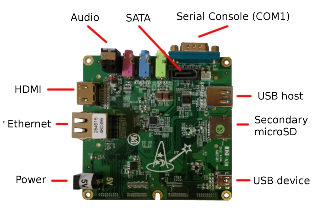
The following two images show the bottom and top views of the Wandboard, where we can see some interesting things. Here are the features of the bottom side of the board:
The RS-232 9-pins connector COM1 can be used to access the serial console
The USB mini port used as USB OTG connector
The USB host port
The secondary microSD connector
The power connector
The Ethernet connector
The audio ports
The SATA connector
The HDMI connector
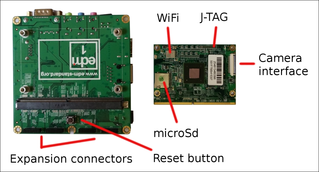
On the top side (we split the core module on the left and the interface board on the right) we have:
The camera interface connector
The primary microSD
The Wi-Fi chip
The four expansion connectors
The reset button can be used to reset the board
This board too can act as a PC, and that's why we will install a complete Debian distribution on it too. This board, as in the case of the BeagleBone Black, has a HDMI connector for external monitor.