Book Image

Intel Edison Projects

By : Avirup Basu
Book Image

Intel Edison Projects

By: Avirup Basu

Overview of this book

Change the way you look at embedded electronics with Intel Edison. It is a small computing platform packed with a set of robust features to deliver hands-on performance, durability, and software support. This book is a perfect place to kickstart development and rapid prototyping using Intel Edison. It will start by introducing readers to the Intel Edison board and explaining how to get started with it. You will learn how to build a mini weather station, which will help you to acquire temperature and smoke level and push it to the IoT platform. Then you will see how to build a home automation device and control your appliances using an Android app. Furthermore, we will build a security system using a webcam to detect faces and perform voice recognition. Toward the end, the book will demonstrate how you can build two robots, which will be based on different line sensing sensors and can be controlled by a PC. The book will guide the readers through each and every step of execution of a project, using Intel Edison.
Table of Contents (7 chapters)

Arduino IDE

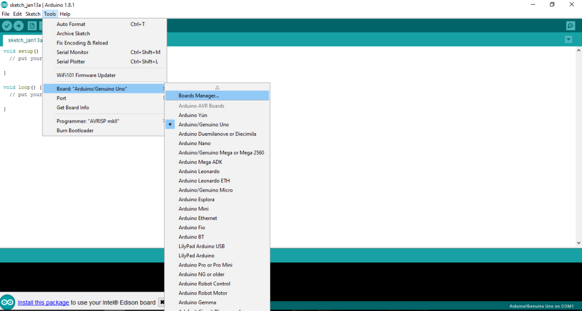
The Arduino IDE is a famous, and widely used, integrated developer environment that not only covers Arduino boards but also many other boards of Intel including Galileo, Edison, Node MCU, and so on. The language is based on C/C++. Once you download the Arduino IDE from the link mentioned at the beginning of this chapter, you may not receive the Edison board package. We need to manually download the package from the IDE itself. To do that, open up your Arduino IDE, and then go to Tools | Board: "Arduino/Genuino Uno" | Board Manager...:

Arduino IDE

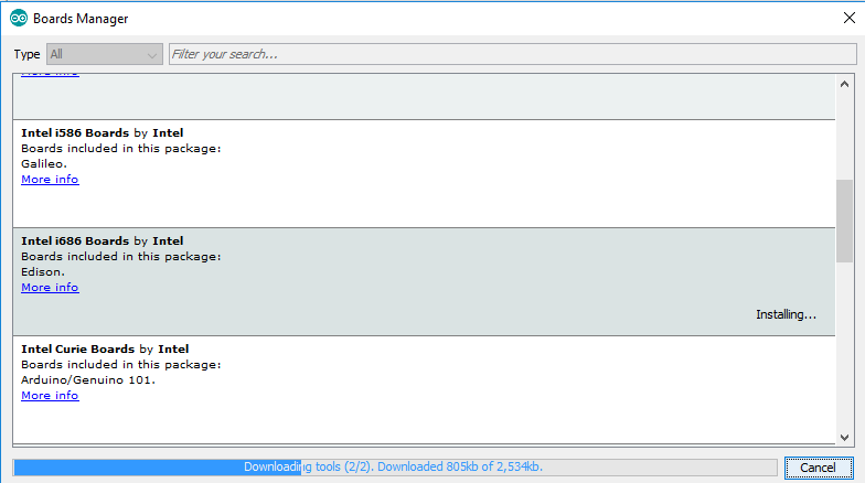
You now need to click on Boards Manager and select Intel i686 Boards. Click on the version number and then click on Install. Boards Manager is an extremely important component of the IDE. We use the Boards Manager to add external Arduino-compatible boards:

Boards Manager

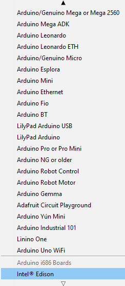
Once installed, you should see your board displayed under Tools Boards:

Board installation successful

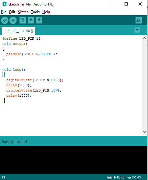
Once successfully installed, you will now be able to program the device using the IDE. Like every starter program, we'll also be burning a simple program into the Intel Edison which will blink the on-board LED at certain intervals set by us. Through this, the basic structure of the program using the Arduino IDE will also be clear. When we initially open the IDE, we get two functions:

  • void setup()
  • void loop()

The setup function is the place where we declare whether the pins are to be configured in output mode or input mode. We also start various other services, such as serial port communication, in the setup method. Depending on the usecase, the implementation changes. The loop method is that segment of the code that executes repeatedly in an infinite sequence. Our main logic goes in here. Now we need to blink an LED with an interval of 1 second:

#define LED_PIN 13 
void setup()
{
pinMode(LED_PIN, OUTPUT);
}

void loop()
{
digitalWrite(LED_PIN, HIGH);
delay(1000);
digitalWrite(LED_PIN, LOW);
delay(1000);
}

In the preceding code, the line #define LED_PIN 13 is a macro for defining the LED pin. In the Arduino expansion board, an LED and a resistor is already attached to pin 13, so we do not need to attach any additional LEDs for now. In the setup function, we have defined the configuration of the pin as output using the pinMode function with two parameters. In the loop function, we have initially set the pin to high by using the digitalWrite function with two parameters, and then we've defined a delay of 1,000 miliseconds which is equivalent of 1 second. After the delay, we set the pin to low and then again define a delay of 1 second. The preceding code explains the basic structure of the Arduino code written in the Arduino IDE.

To burn this program to the Edison device, first compile the code using the compile button, then select the port number of your device, and finally click the Upload button to upload the code:

Arduino IDE — blink

The port number can be selected under Tools | port.

Now that we know how to program using an Arduino, let's have a look at how it actually works or what's happening inside the Arduino IDE.

A number of steps actually happen while uploading the code:

  1. First, the Arduino environment performs some small transformations to make sure that the code is correct C or C++ (two common programming languages).
  2. It then gets passed to a compiler (avr-gcc), which turns the human readable code into machine readable instructions (or object files).
  3. Then, your code gets combined with (linked against), the standard Arduino libraries that provide basic functions such as digitalWrite() or Serial.print(). The result is a single Intel hex file, which contains the specific bytes that need to be written to the program memory of the chip on the Arduino board.
  4. This file is then uploaded to the board, transmitted over the USB or serial connection via the bootloader already on the chip or with external programming hardware.

Python

Edison can also be programmed in Python. The code needs to be run on the device directly. We can either directly program the device, using any editor, such as the VI editor, or write the code in the PC first, and then transfer it using any FTP client, like FileZilla. Here we'll first write the code using Notepad++ and then transfer the script. Here also, we'll be executing a simple script which will blink the on-board LED. While dealing with Python and hardware, we need to use the MRAA library to interface with the GPIO pins. This is a low-level skeleton library for communication on GNU/Linux platforms. It supports almost all of the widely-used Linux-based boards. So, initially you need to install the library on the board.

Open up PuTTY and log in to your device. Once logged in, we'll add AlexT's unofficial opkg repository.

To do that, add the following lines to /etc/opkg/base-feeds.conf using the VI editor:

src/gz all http://repo.opkg.net/edison/repo/all
src/gz edison http://repo.opkg.net/edison/repo/edison
src/gz core2-32 http://repo.opkg.net/edison/repo/core2-32

Next, update the package manager and install git by executing the following commands:

opkg update
opkg install git

We'll clone Edison-scripts from GitHub to simplify certain things:

git clone https://github.com/drejkim/edison-scripts.git ~/edison-scripts

Next we'll add ~/edison-scripts to the path:

echo 'export PATH=$PATH:~/edison-scripts' >> ~/.profile
source ~/.profile

We'll now run the following scripts to complete the process. Please note that the previous steps will not only configure the device for MRAA, but will also set up the environment for later projects in this book.

Firstly, run the following script. Just type:

resizeBoot.sh
Then go for
installPip.sh

The previous package is the Python package manager. This will be used to install essential Python packages to be used in a later part of this book. Finally, we'll install Mraa by executing the following command:

installMraa.sh

MRAA is a low-level skeleton library for communication on GNU/Linux platforms. Libmraa is a C/C++ library with bindings to Java, Python, and JavaScript to interface with the IO on Galileo, Edison, and other platforms. In simple words, it allows us to operate on the IO pins.

Once the preceding steps have completed, we are good to go with the code for Python. For that, open up any code editor, such as Notepad++, and type in the following code:

import mraa 
import time


led = mraa.Gpio(13)
led.dir(mraa.DIR_OUT)

while True:
led.write(1)
time.sleep(0.2)
led.write(0)
time.sleep(0.2)

Please save the preceding code as a .py extension such as blink.py, and now, we'll explain it line by line.

Initially, using the import statements, we import two libraries: MRAA and time. MRAA is required for interfacing with the GPIO pins:

led = mraa.Gpio(13)
led.dir(mraa.DIR_OUT)

Here we initialize the LED pin and set it to the output mode:

while True:
led.write(1)
time.sleep(0.2)
led.write(0)
time.sleep(0.2)

In the preceding block, we put our main logic in an infinite loop block. Now, we will transfer this to our device. To do that again, go to the PuTTY console and type ifconfig. Under the wlan0 section, note down your IP address:

IP address to be used

Now open up FileZilla and enter your credentials. Make sure your device and your PC are on the same network:

  • Host: The IP address you got according to the preceding screenshot: 192.168.0.101
  • Username: root because you will be logging in to the root directory
  • Password: Your Edison password
  • Port: 22

Once entered, you will get the folder structure of the device. We'll now transfer the Python code from our PC to the device. To do that, just locate your .py file in Windows Explorer and drag and drop the file in the FileZilla console's Edison's folder. For now, just paste the file under root. Once you do that and if it's a success, the file should be visible in your Edison device by accessing the PuTTY console and executing the ls command.

Another alternative is to locate your file on the left-hand side of FileZilla; once located, just right-click on the file and click Upload. The following is the typical screenshot of the FileZilla windows:

FileZilla application

Once transferred and successfully listed using the ls command, we are going to run the script. To run the script, in the PuTTY console, go to your root directory and type in the following command:

python blink.py

If the file is present, then you should get the LED blinking on your device. Congrats! You have successfully written a Python script on your Edison board.