

Understanding the part
The first thing we need to do before creating a proper CAM setup is focus on the shape of our part. We want to aim to have a complete understanding of the part’s geometries, tolerances, and surface finish. Not concentrating on analyzing the part may lead to different machining approaches; that’s why it is so important to take our time and check the drawings with the highest attention.
In the next few pages, we will explain how to machine the following part on a three-axis machine. The following figure shows a 2D drawing of the part we will be looking at:
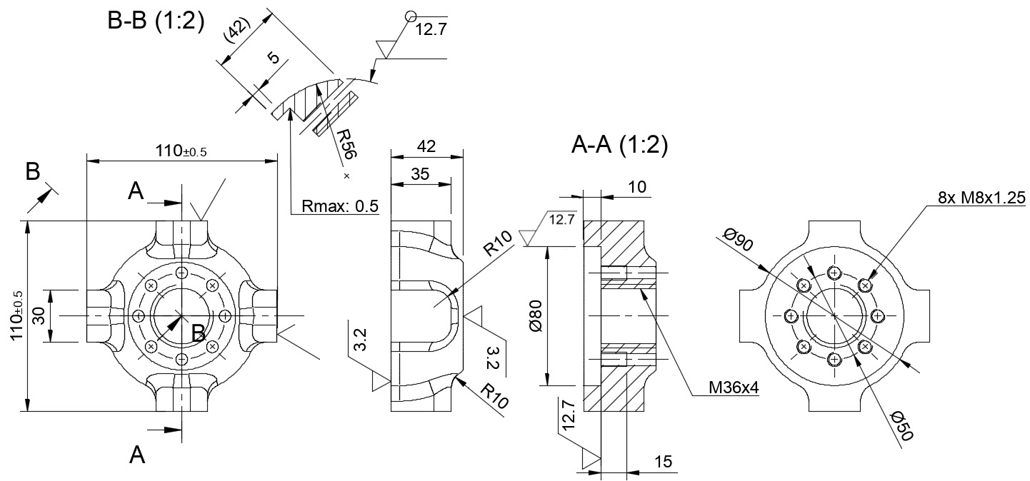
Figure 8.1: Part 2D drawing
What data can we extrapolate from this drawing?
- The component’s overall dimensions are 110 x 110 x 42 mm.
- On the two planes defined by the 42 mm dimension, a good surface finish (3.2 microns) is required, so we should use a stock thicker than 42 mm and then machine it down to 42 mm with a finishing pass. For example...