

Approaching a lathe and its components
Turning, long story short, it is a very old machining technique discovered thousands of years ago. While understanding Egyptian pottery may sound interesting to some, it is definitely out of the scope of this book, so we are going to jump right into the action!
Turning is a mechanical process where a cylindrical part is put on fast rotation, and then approached by a cutting tool that progressively removes material from it. The machine that lets us shape our part with this technique is called a lathe.
If you ask a professional CNC user, they will tell you that a lathe is a rather complex machine that consists of many components such as the saddle, the tailstock, the headstock, and so on. Don’t worry about all these intimidating words—we will approach turning in the simplest way possible. In the following screenshot, we can find a lathe stripped up to the bones:
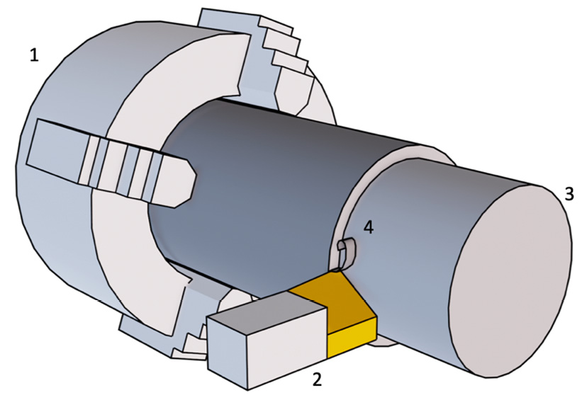
Figure 1.1: Lathe main actors
Ultimately, there are only four actors involved in turning:
- Chuck: A fast-spinning clamping device; it holds the stock to be machined
- Cutting tool: A special hard-metal blade that removes material from the stock
- Machined stock: Our part before machining is completed
- Chip: The removed particles and filament (waste material)
If you have ever approached a working lathe, I’m sure you noticed that the material shape about to be machined—the stock—spins very fast, while the cutting tool moves quite slowly, with a lot of chips being generated and projected all over the surrounding environment.
Even if the chip is valueless, it doesn’t mean that we can pretend it doesn’t exist; if we did, it would very easily render our part and our tool valueless. Controlling chip formation is very important (not only for turning) because it has the bad habit of becoming an entangled mess (a little bit like pasta) and damages everything it comes into contact with.
There are several types of lathes on the market; some are really big and some are very complex, but at the end of the day, all of them are pretty similar to one another.
Now that we understand the main components of the lathe, we can dive just a little bit into the theory behind such an incredible machine!
Cylindrical coordinate system
In order to understand coordinates, we need to remember that we live in a 3D world. In our world, in order to specify the location of an object with exact precision, we must provide a set of three numbers (coordinates) that measure the distance from a point in space—the origin—in a given direction.
In our daily lives, we often use Cartesian coordinates; here, we have a few examples:
- When working in an Excel file or when playing Battleship, in order to locate a cell, we need to know the row number and column number (2D Cartesian coordinates)
- If we want to give the dimensions of an object, we must provide the length, the width, and the height (3D Cartesian coordinates)
However, as mentioned, all the examples previously listed are Cartesian coordinates, where coordinates are expressed as a length along axes oriented at 90° from each other.
Orienting all the axes at 90° is generally the best approach for parts with a cubic shape, however, when it comes to lathes, a different coordinate system may be better. This is because all parts machined with a lathe have an axial symmetry, meaning that basically every part looks more or less like a cylinder. Therefore, we can use cylindrical coordinates instead.
With cylindrical coordinates, we do not express a point position with three distances; we express a position with an angle and two distances. We can see this in the following screenshot:
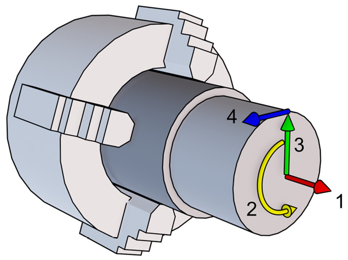
Figure 1.2: Cylindrical coordinates’ components
Let’s specify what the labels mean:
- The red arrow is the axial direction (longitudinal), which is the rotation axis.
- The yellow arrow is the rotation angle (
 ).
). - The green arrow is the radial direction. Note that the arrow is not static; you can pretend it is a hand of a clock, where all the ticks on the dial would be a possible radial direction. There are infinite green arrows around the rotation axis, each rotated by an angle (
 ) from 0° to 360°!
With these three numbers, we already can specify with extreme precision every single point inside and outside our stock. However, it will be useful to introduce another direction.
- The blue arrow is the tangential direction. It may not be so simple to understand the tangential direction, but we can just say that it is a vector that starts from the tip of a radial vector with a direction perpendicular both to the radial vector and to the axial vector.
Now that we know a bit more about cylindrical coordinates, we can start using this knowledge to differentiate between turning operations!
Different types of turning operations
To discuss the different types of turning operations, we will look at the two main families of machining:
- External machining
- Internal machining
Let’s take a look at these in more detail.
External machining
These operations are the most common operations performed while turning. In this type of process, the material is removed from “outside-in” along the radial direction. This basically means that the average radial coordinate of our tool will keep reducing during the operation.
In the following screenshot, we have a typical external machining operation depicted:
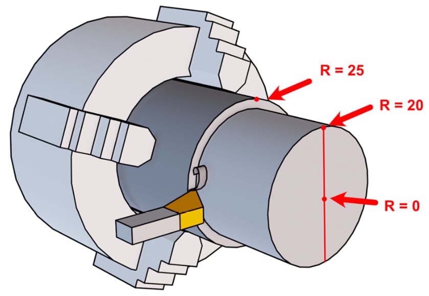
Figure 1.3: External machining example
Just by glancing at the figure, we should understand that the tool starts on the outside of our part where the radial coordinate is at the maximum, while machining it will progressively reduce it when moving toward the center (where the radial coordinate is 0).
Since, as we will discover, there are many different types of machining strategies, it is a bit difficult to find a strict definition for external machining; however, everything will be clearer when compared to the next machining approach.
Internal machining
These operations are different from the previous case since the material is removed “inside-out.” So, the average radial coordinate for our tool is growing during the operation:
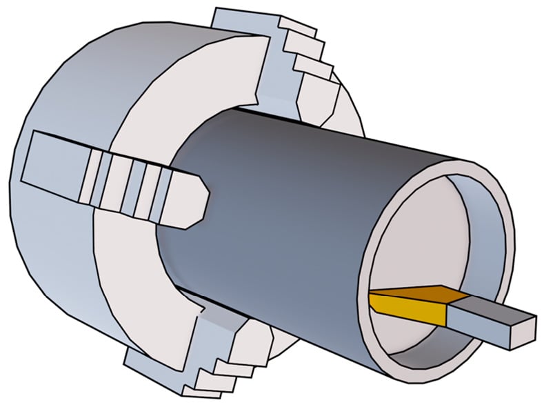
Figure 1.4: Internal machining example
As you can see from the previous screenshot, the tool is moving inside our stock, and the cut chip may find itself stuck in the cavity since there is material all around the tool. As you can also see, the tool is still quite visible, but there are cases where we may completely lose the line of sight after a certain depth, and this is not good for beginners.
As a matter of fact, when we first approach turning, it is always a good idea to look constantly at our part while being machined since we can check the surface finish, prevent unforeseen collisions with parts of the stock or parts of the lathe, and monitor chip evacuation. For all these reasons, internal machining may be a bit trickier than external machining.
Note
As a rule of thumb, if the forming chip is somehow free to flow and falls on the ground, we are in external machining; if it can be stuck inside, we are in internal machining.
It is now time to explore something a bit more technical but really important to understand: working parameters!