

Exploring main machining strategies
When we plan how to machine our part out of the stock, we have to think like a chess master. What I mean by this is that we have several pieces we can play with, but in order to win the game, we have to use every component in the best possible way it can be used. Therefore, we need to plan which piece to play first and with which type of move: do we move the bishop or the queen? Do we move by one square at a time or full speed ahead?
In the following sections, we are going to discover the main moves we can play with when it comes to turning.
Longitudinal operations
Longitudinal machining is a simple and common operation strategy, suitable for rough machining with high power and strong tools. Let’s check a basic example in the following screenshot:
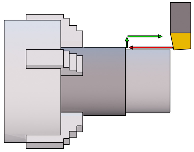
Figure 1.11: Longitudinal machining approach
The typical approach for longitudinal operations is to move the tool on the front of our stock (at a safe distance), set the cutting depth in the radial direction, and then move the tool forward. As we can see in the screenshot, while cutting, our tool is moving along the axial direction only, so we have a constant cutting speed per cutting pass. Once at the desired distance, the tool will disengage our stock radially and then repeat the process until the right diameter is machined.
Since this is longitudinal machining, the main cutting direction is on the longitudinal axis at a given radial distance; therefore, after a chuck rotation, our tool will be moved by one feed step along the longitudinal direction.
As a recap, in this type of machining, the cutting feed is along the axial direction, while the cutting depth is fixed and constant and is measured along the radial direction. As we are about to discover, there are other machining strategies where what we just said doesn’t apply.
Facing operations
Facing is used when we need to clean the front face of our stock:
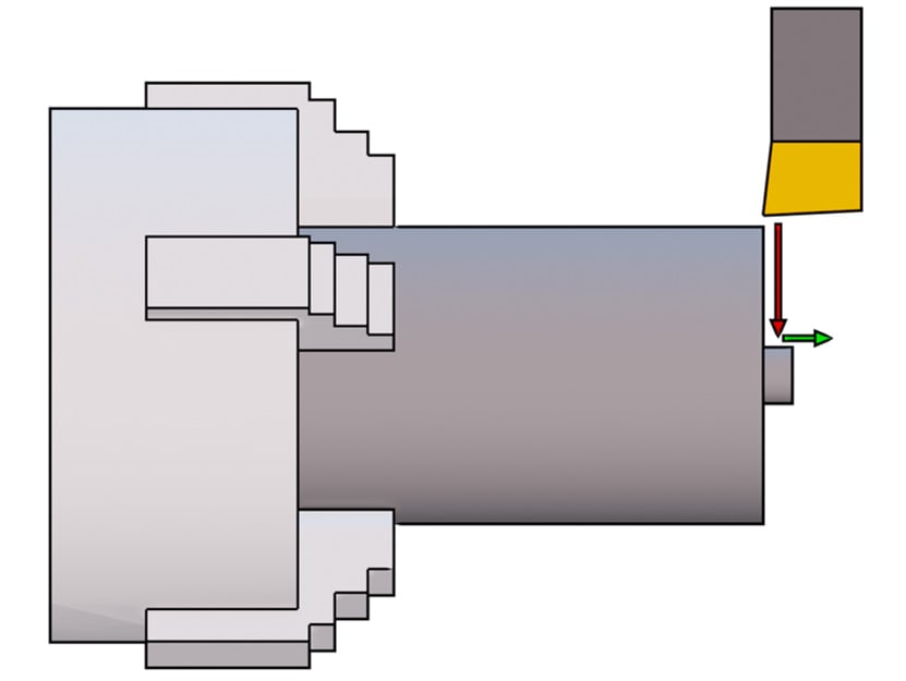
Figure 1.12: Facing machining approach
As shown here, while cutting, our tool is moving in the radial direction only; therefore, the cutting power will keep changing unless we adjust the feed or rotation speed accordingly.
The standard approach for facing operations is to move the tool at a safe distance in the radial direction, set the cutting depth in the axial direction, and then approach the stock radially. Once at the desired position, the tool will disengage our stock axially and then repeat the process until the right length is machined.
Since in facing, we are basically cleaning a slice of our stock, we are operating at a fixed axial coordinate and our tool is moving radially. So, after a chuck rotation, our tool will be moved forward by one feed step along the radial direction.
As a recap, when facing, the cutting feed is along the radial direction while the cutting depth is along the axial direction (this is different than longitudinal operations!).
Plunging operations
Plunging is similar to facing since the tool is moving in the radial direction only; however, because plunging is used for grooving or cutting, the tool is much slimmer. That’s because circlips grooves can be very thin, and our tool needs to fit inside them. Another reason is that when cutting our part, it is not a good idea to perform a large cut because that would require a lot of material removed without a real need.
As already mentioned for facing, since radial coordinates are always changing, so does the cutting power, unless controlled by feed changes or RPM.
As shown in the following screenshot, the typical approach for plunging is to position our tool at a safe radial position, set the desired axial coordinate, and then approach the part radially:
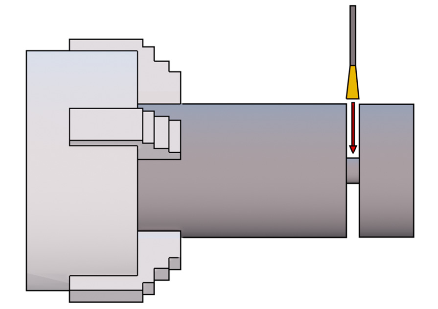
Figure 1.13: Plunging machining approach
So, to recap this strategy, plunging is similar to facing since it has feed along the radial direction too, but the main difference is that we cannot set the cutting depth since the tool cutting edge is always engaged entirely; therefore, the cutting depth is always at the maximum possible value!
Profiling operations
Profiling is one of the most complex operations since the tool moves constantly radially and axially. Let’s check the following screenshot for an idea of how profiling works:
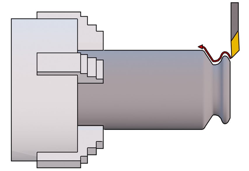
Figure 1.14: Profiling machining approach
As shown in the screenshot, the motion path of our tool can be very complex; therefore, this type of operation is the most flexible and is well suited for finishing our part. However, due to the fact that the cutting direction is not constant, there is always the risk of impact between the tool and our stock. As you may have noticed in the screenshot, after “climbing the first hill,” our tool will likely collide with the stock since the required path is too steep for the tool to pass.
To reduce the possibility of errors, an impact simulation is always a good idea in CAM, but for complex machining operations such as profiling, you must always check the results. Especially when a beginner is approaching turning for the first time, 99% of the time they will discover that the back of the tool or the shank will collide where the profile gets too steep or too narrow.
If we want to analyze what happens to our cutting parameters when profiling, we have to remember that the profile is not constant along the radial direction nor along the longitudinal direction; it keeps changing. So, unless our chuck is able to control rotation according to the tool’s radial position, the cutting speed will not be constant.
Having said that, we also need to remember that feed is measured along the cutting direction, so it will keep changing along the profile; the same can also be said for cutting depth.
Finally, we are at the end of yet another section. There is only one last major topic to cover: tool geometry.