

Understanding tool geometry
As we discovered, there are many possible operations and geometries that we can machine on our lathe, but not every tool is suitable for every operation (always remember the chess analogy). We are now going to classify tool geometry in order to recognize, at first glance, which tool is more suitable for which machining strategy.
We can split the geometry of a cutting tool into three main categories:
- Tool edges
- Tool surfaces
- Tool angles
Let’s start with our deeper analysis of the geometry.
Tool edges
In the following screenshot, we can see a tool with a transparent shank where the edges are highlighted:
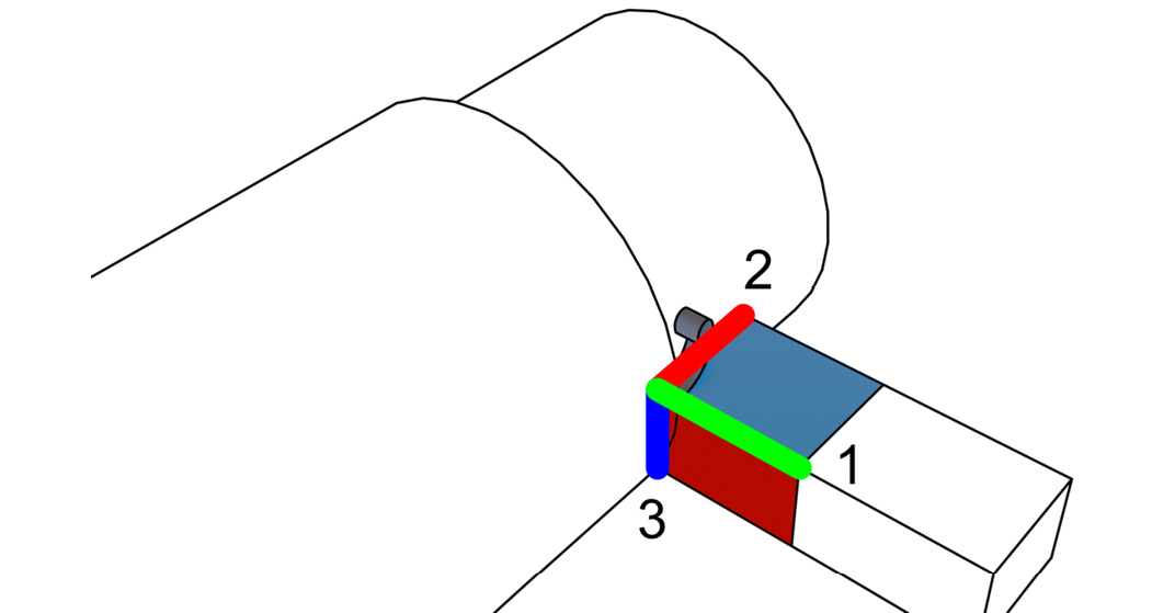
Figure 1.15: Main tool edges highlighted
You’ll notice that the tool shown is very crudely drawn and is simply a square. In reality, as we are going to discover, tool geometry is way more complex; however, at the moment, we will pretend it is a real tool since understanding surfaces and edges will be simpler this way.
- The main cutting edge
- The auxiliary cutting edge
- The nose edge
Cutting edge
As the name suggests, the cutting edge is a sharp edge that cuts our stock that is rotating against it. The cutting edge simply cuts along the feed direction and cuts the main portion of the chip.
Auxiliary cutting edge
In order to cut the stock, we need to cut in two directions. So, the auxiliary cutting edge cuts the side of the chip and removes the material from the stock.
Nose edge (radius)
The nose edge is not a real “edge.” It is never sharp because it wouldn’t last a single second while machining; instead, it is a “smooth edge” with a specific radius that can be bigger or smaller according to the tool we choose. A tool with a bigger nose radius will be less sharp and therefore will be able to sustain higher feed rates and higher cutting depths for a longer time.
Saying that, it is important to note that the nose radius is responsible for the surface’s finish. As you can see here, from a geometrical point of view, a higher nose radius will lead to less surface roughness when machining, and therefore to a better surface finish:
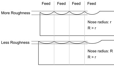
Figure 1.16: Changing the nose radius will change surface roughness
So, it looks like you may always want to use a large nose radius for roughing and for finishing… well, not so fast—there is a catch! When working at a low cutting depth (for example, when finishing a flexible part), a big nose radius will generate higher radial forces that are going to create strong vibrations (more details on that in the Entering angle (KAPR) section at the end of this chapter). Such vibrations will ruin the surface finish. A tool with a small nose radius will be super sharp and short-lasting, but also incredibly more effective at small cutting depths when finishing.
Now that we have learned something about the three main edges of every tool, let’s now start talking about the three main surfaces and their relative orientation.
Tool surfaces
All the edges listed up until now come into contact at the tip (or the nose) of the part. Three main surfaces are defined from this intersection. As always, it is way easier to understand the geometry by looking at a simple example:
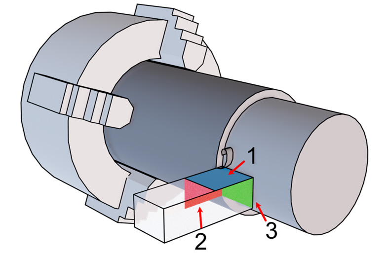
Figure 1.17: The main surfaces of a tool
Here, we can see three highlighted surfaces to study:
Let’s take a look at them.
Rake surface
The rake surface is the surface generated between the main cutting edge and the auxiliary cutting edge. It is the surface our chip is rubbing against before being evacuated. As you can imagine, much of the cutting power is transmitted to the stock through the cutting edge and the rake surface. At the moment, there is not much more to say about it, but as we will shortly discover, the main point of interest is its rotation.
Tool flanks
In our tool, we have two flanks:
- The main flank is generated between our cutting edge and our nose edge
- The auxiliary flank is generated between our auxiliary cutting edge and our nose edge
After that quick look at surfaces, let’s analyze angles.
Tool angles
When machining our part, we have many angles involved; some angles are related to the tool shape, while others are related to the way our tool is installed on the lathe.
Rake angle
The rake angle (  ) is the angle that describes how much our rake surface is rotated around the cutting edge. We can classify tools according to their rake angle, and we can distinguish three types of tool families: negative tools, neutral tools, and positive tools.
In the following screenshot, we can see those three tools, from left to right respectively:
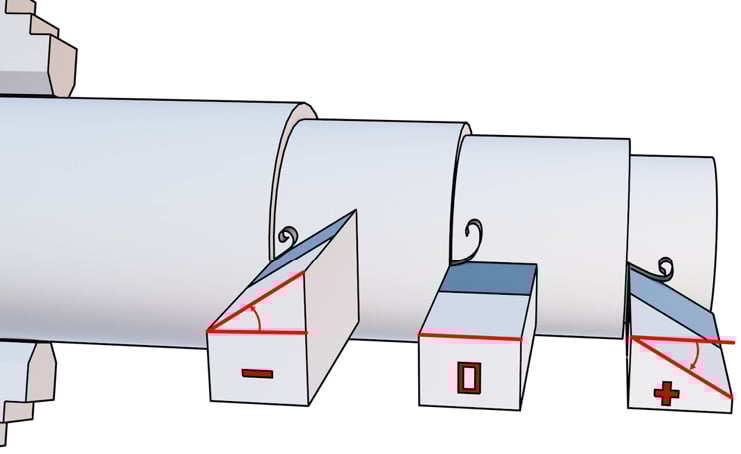
Figure 1.18: Rake angle visualized
More positive values will result in a super sharp tool (with a lower life span) capable of an easy-flowing chip very suitable for a surface finish.
More negative values will result in a stronger tool with a higher life span. Since the cutting edge is not so sharp, the tool will be great for roughing passes with higher cutting depth. As you can see in the screenshot, negative rake angles impose a hard twist in the forming chip; therefore, it won’t flow so easily and will break into smaller particles that may rub against the machined surface.
There is not much to say about neutral tools—their properties are a mix between positive tools and negative tools.
Please note that there is also a less important rake angle measured from the auxiliary cutting edge:
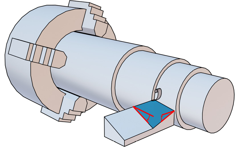
Figure 1.19: Rake angles
In the screenshot, we can find the main rake angle on the left and the auxiliary rake angle on the right.
Relief angle
When introducing tool flanks, we missed one important thing—they should never rub or collide against our stock or our machined part.
As you can imagine, the only part of our tool that should ever rub against our stock is our cutting edge(s). In the tools seen up until now, there is actually a really large surface rubbing against the machined part. Let’s analyze the following screenshot for a better understanding of what is going on:
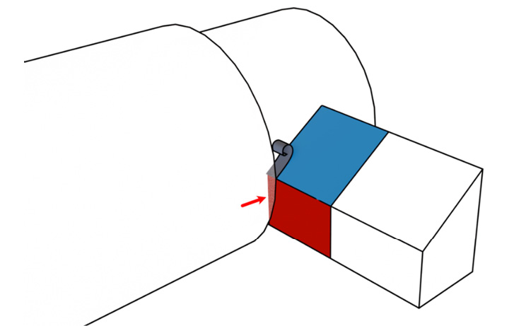
Figure 1.20: Friction area for a squared tool
As shown in the screenshot by the arrow, all that area is rubbing against the machined side! Not good at all! The same is true on the other flank.
To prevent this type of behavior, in real life, the two flanks are always rotated along the cutting edges by a relief angle in order to avoid friction. Every tool always has relief angles, and the angle value cannot be negative; otherwise, cutting edges would never engage the stock (because the bottom of the flank will hit the stock first):
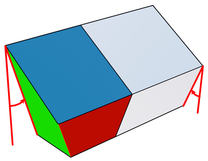
Figure 1.21: Relief angles displayed
We can find in the previous screenshot the auxiliary relief angle (on the left) and the main relief angle (on the right). These angles avoid friction with the turning stock while machining.
Nose angle
While looking at all the tools displayed up until now, you may have noticed that the angle between our cutting edge and our auxiliary cutting edge—called the nose angle—is constantly 90°. Just in case you are wondering… more often than not, this is not true; there are many different shapes available on the market!
Let’s check the following screenshot to grasp what the nose angle is:
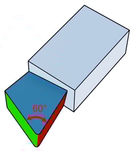
Figure 1.22: Nose angle visualized
Why don’t we try to analyze the tool shown in the screenshot? We should have lots of ways to analyze it. At the first glance, we should recognize that it is a positive tool (but almost neutral), that it has small relief angles on the two flanks, and as measured by the arrow, the nose angle is 60° with a small nose radius as well. Not bad!
This is a somewhat old type of tool; it has a large drawback: once the cutting edge or rake surface is really damaged, we have to throw it in the bin and buy a new tool. Today, the most typical approach is to have a tool composed of a shank and a swappable insert that can be replaced without changing the entire tool.
In the following screenshot, we can see on the left we have an “old-style” tool made in a single piece, while on the right side, we have a tool shank and a replaceable insert (both have the same cutting geometry):
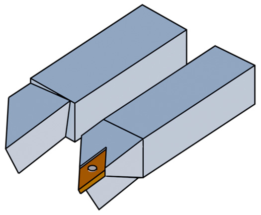
Figure 1.23: Insert versus solid tool
Also, please note that most of these inserts are symmetrical, so they have multiple cutting edges; once one of them is spent, we simply rotate the same insert and keep spinning the chuck!
In the following table, you will find a few typical insert examples with different nose angles and their suggested use:
|
TOOL SHAPE |
|||||||
|
Name |
R (Round) |
S (Square) |
C (Rhombic 80°) |
W (Trigon) |
T (Triangle) |
D (Rhombic 55°) |
V (Rhombic 35°) |
|
Preview |

|

|

|

|

|

|

|
|
Nose angle |
0/90° |
90° |
80° |
80° |
60° |
55° |
35° |
|
TOOL USAGE |
|||||||
|
Versatility |
0 |
0 |
+++ |
++ |
++ |
+++ |
+ |
|
High-depth roughing |
+++ |
+++ |
++ |
+ |
+ |
0 |
0 |
|
Low-depth roughing |
0 |
+ |
++ |
+++ |
++ |
+ |
0 |
|
Finishing |
0 |
0 |
+ |
++ |
+++ |
+++ |
+++ |
|
Profiling |
0 |
0 |
0 |
+ |
++ |
+++ |
+++ |
Figure 1.24: Tool specifications and typical use
The table shown is divided into two sections. The first part is related to the tool shape, where we can find the seven different families, their naming convention, and their shape. The second part of the table rates tool usage from “+++” to “0” (with “++” and “+” values in the middle). Let’s review the usages:
- Versatility: If we were alone on a desert island with our lathe, which tool would we take with us? A higher ranking (“+++”) means that that tool is a good choice in many situations and can more or less do everything. It is a workhorse and not choosy!
- High-depth roughing: If we need to remove a lot of material with rough passes at high cutting depth and high power, we need a very strong tool. A higher ranking (“+++”) means that the tool is tough and long-lasting, while a lower ranking (“0”) means that the tool is super sharp and will likely break or wear immediately.
- Low-depth roughing: In this scenario, we still need to perform roughing passes but with a thinner cutting depth. This case is somewhere between a roughing pass (where we remove a lot of material and we don’t mind about tolerances and surface quality) and a finishing pass (where we try to get good surface quality and tight tolerances). I decided to include it just to let you note that at low cutting depth, the round shape is very bad because it causes vibrations (this will be described later in the Entering angle (KAPR) section).
- Finishing: If we need to finish our part, we probably need to remove a thin layer of material. A higher ranking (“+++”) means a super sharp tool suitable for a good surface result.
- Profiling: With this ranking, we are going to evaluate which tool is better for machining complex profiles. A higher ranking means that the tool is very good and that it is not limited by accessibility issues, while a lower ranking means that the tool may often collide with the stock. The main difference between profiling and finishing is that the profiling score also considers shape accessibility.
We just mentioned shape accessibility—what does that mean? The answer is simple: slim and sharp tools can reach areas beefier and stronger tools cannot. Let’s check the following screenshot:
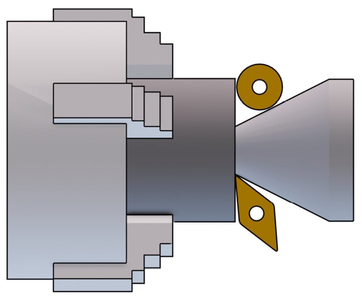
Figure 1.25: Different accessibility displayed
As we notice at the first glance, the round tool (type R) cannot remove as much material as a rhombic tool (type D) because the area to be machined is too deep to reach for it.
We have just taken a look at all the angles that we can find when looking at a tool on the workshop shelf. Is this the end? Not really—despite the tool shape, we can always decide to mount it rotated! Let me introduce you to the entering angle.
Entering angle (KAPR)
The entering angle is the angle measured from the feed direction to the cutting edge.
Changing the entering angle can dramatically change tool performance and chip management. In normal circumstances, it is always a good idea to set the KAPR close to 90°. With flexible parts, we should never set an entering angle lower than 70° if possible. The reason is pretty simple: changing the angle is actually changing the way our cutting edge is transferring power to the stock material:
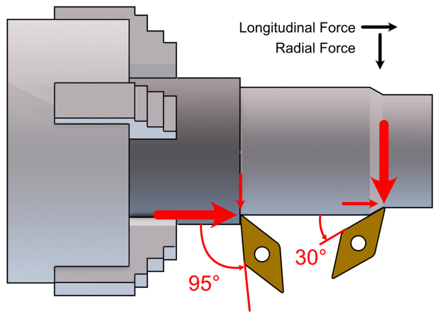
Figure 1.26: The same insert mounted at different KAPR angles
As shown on the left of the screenshot, when close to 90°, our tool is transferring power mainly in the longitudinal direction, and only a small percentage of the total is transferred as the radial component.
On the right, we can see that the tool is far from 90°, and therefore the radial component is much higher; this is bad, especially with flexible parts, because they will bend.
Why is bending a bad thing? Let’s review the following screenshot for a better understanding:
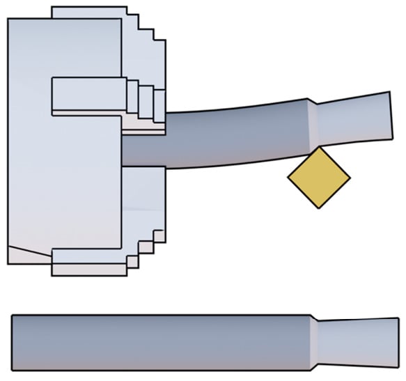
Figure 1.27: Bending
As you can see, the screenshot depicts a scenario where a slim part is machined with a longitudinal operation. Other than that, we can see that the tool has a 45° entering angle and a high cutting depth, which is the perfect recipe for high radial forces that will bend the part while machining.
As you can see at the top of the screenshot, the stock is heavily bent while machining, so we can imagine high vibrations due to the runout of the center rotation line and low surface quality.
As we can find at the bottom of the screenshot, after the machining is completed, what should have resulted in a nice cylindrical surface appears more like a cone with a higher diameter where the bending was more severe!
It may look like a small entering angle is forbidden, but not so fast. There are many different scenarios where we may have to use small angles; here are some examples:
- When we want to improve tool life span: At the same cutting depth, with a smaller entering angle, a bigger part of our cutting edge is engaged, and therefore the cutting force will be distributed over a bigger area with smaller stress on the insert that will last longer.
- When we want to machine a thread: Let’s take a look at the following screenshot for a better understanding of this example:
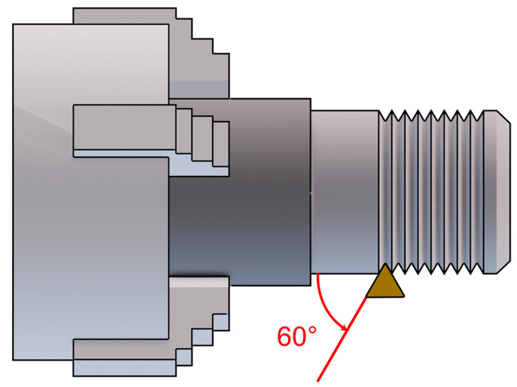
Figure 1.28: Threading operation displayed
As shown in the previous screenshot, when threading we must use an entering angle and a nose angle strictly dictated from the thread specs: 60° as KAPR and 60° as the nose angle (for most metric threads); that’s why the triangle insert is very often used for threading.
As we already mentioned, remember that when threading, many parameters are locked to thread specs: from the thread pitch, we must impose a certain feed step, and from the thread angle, we must use a tool with a specific nose angle, entering angle, and maximum nose radius. Do not underestimate the nose radius when threading: if it’s too large (over thread specs), the nut will not be able to be screwed on.
So, when threading, if we need to reduce vibrations or bending, there is only one parameter left… we can change the cutting depth only.
As a bonus point, let’s explain why the round tool shape can be a good choice at high cutting depth but may generate high vibrations at low cutting depth. Let’s analyze the following screenshot:
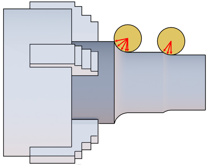
Figure 1.29: Round-tool KAPR
As you can see, the tool on the left is cutting at a high cutting depth; therefore, it is exchanging all the cutting force on a wide range of angles, from almost 90° to 0°, so the radial force generated is not a main issue. On the other hand, the tool on the right is engaging a thin layer only, and the cutting force is shared from almost 0° to 0°. Such a small KAPR will create massive vibrations—that’s why round tools are good for high-depth machining but not so much for low depths (and the same can be said for the nose radius).
When facing, a round tool may become handy even at low cutting depth since we don’t care that much if the force is transferred to the chuck!
There are many more formulas related to the entering angle, but they are probably way beyond the scope of this book, so we won’t deal with them. A last tip on the subject, though: just note that the entering angle is also responsible for the chip shape, so remember that the smaller the entering angle, the thinner and the wider the chip (and vice versa).
As shown in this last section, we should always pay close attention to the shape of the tools since they may look similar, but in reality, they are very different and may be the cause (or the solution) of many machining-related problems.