

Now is the time for building our own talking logic probe. Follow these steps:
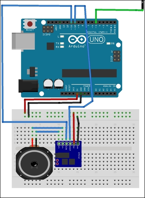
Wire the talking logic probe circuit on a solderless breadboard, as shown next. For reference, the circuit schematic diagram has been provided here:

Upload the talking logic probe code to the Arduino using the sketch given after the schematic diagram.
The phrase Signal is Low will be heard through the talking logic probe's speaker.
Touch the logic probe's green test lead onto the EMIC 2 TTS module's +5 V pin.
The phrase Signal is High will be heard through the talking logic probe's speaker.
The code required to make the talking logic probe operational is:
/*

  Talking Logic Probe

  Author: Don Wilcher 2014 14 11

  Program Description:

  This program allows tracing digital circuit signals using the Emic 2 Text-to-Speech
  Module. Detecting a high or low signal will allow the Emic 2 TTS module to speak one of the voltage levels present.

*/

// include the SoftwareSerial...