

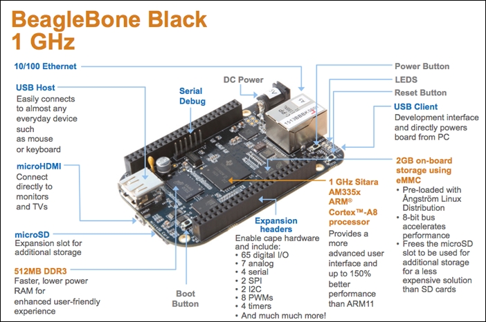
A picture is worth a thousand words. The following picture describes about the hardware specifications of the BeagleBone Black. But you will get some more details about every part of the board as you read the content in the following picture.
If you are familiar with the basic setup of a computer. You will know that it has a CPU with RAM and Hard Disk. To the CPU you can connect your Keyboard, Mouse, and Monitor which are powered up using a power system.
The same setup is here in BeagleBone Black also. There is a 1GHz Processor with 512MB of DDR3 RAM and 4GB on board eMMC storage, which replaces the Hard Disk to store the operating system. Just in case you want more storage to boot up using a different operating system, you can use an external microSD card that can have the operating system that you can insert into the microSD card slot for extra storage.
As in every computer, the board consists of a power button to turn on and turn off the board and a reset button to reset the board. In addition, there is a boot button which is used to boot the board when the operating system is loaded on the microSD card instead of the eMMC. We will be learning about usage of this button in detail in the installing operating systems topic of this chapter.
There is a type A USB Host port to which you can connect peripherals such as USB Keyboard, USB Mouse, USB Camera, and much more, provided that the Linux drivers are available for the peripherals you connect to the BeagleBone Black.
Tip
It is to be noted that the BeagleBone Black has only one USB Host Port, so you need to get an USB Hub to get multiple USB ports for connecting more number of USB devices at a time. I would recommend using a wireless Keyboard and Mouse to eliminate an extra USB Hub when you connect your BeagleBone Black to monitor using the HDMI port available.
The microHDMI port available on the BeagleBone Black gives the board the ability to give output to HDMI monitors and HDMI TVs just like any computer will give.
You can power up the BeagleBone Black using the DC Barrel jack available on the left hand side corner of the board using a 5V DC, 2A adapter. There is an option to power the board using USB, although it is not recommended due to the current limit on USB ports. We will see about this in detail in the upcoming chapters when we connect USB Wi-Fi dongle and USB camera to the BeagleBone Black.
There are 4 LEDs on board to indicate the status of the board and help us for identifications to boot up the BeagleBone Black from microSD card. The LEDs are linked with the GPIO pins on the BeagleBone Black which can be used whenever needed.
You can connect the BeagleBone Black to the LAN or Internet using the Ethernet port available on the board using an Ethernet cable. You can even use a USB Wi-Fi module to give Internet access to your BeagleBone Black. In Chapter 5, Connecting Physical Computing Systems to the Internet, you will learn how to do this.
The expansion headers which are in general called the General Purpose Input Output (GPIO) pins include 65 digital pins. These pins can be used as digital input or output pins to which you can connect switches, LEDs and many more digital input output components, 7 analog inputs to which you can connect analog sensors like a potentiometer or an analog temperature sensor, 4 Serial Ports to which you can connect Serial Bluetooth or Xbee Modules for wireless communication or anything else, 2 SPI and 2 I2C Ports to connect different modules such as sensors or any other modules using SPI or I2C communication. It also has 8 PWM output pins that can be used for applications like fading and LED or in robotic applications for varying the speed of a motor which we will be discussing later in the upcoming chapters.
We also have the serial debugging port to view the low-level firmware pre-boot and post-shutdown/reboot messages via a serial monitor using an external serial to USB converter while the system is loading up and running. After booting up the operating system, this also acts as a fully interactive Linux console.