Book Image

ESP8266 Internet of Things Cookbook

By : Marco Schwartz
Book Image

ESP8266 Internet of Things Cookbook

By: Marco Schwartz

Overview of this book

The ESP8266 Wi-Fi Module is a self contained System on Chip (SOC) with an integrated TCP/IP protocol stack and can give any microcontroller access to your Wi-Fi network. It is capable of either hosting an application or offloading all Wi-Fi networking functions from another application processor. This book contains practical recipes that will help you master all ESP8266 functionalities. You will start by configuring and customizing the chip in line with your requirements. Then you will focus on core topics such as on-board processing, sensors, GPIOs, programming, networking, integration with external components, and so on. We will also teach you how to leverage Arduino using the ESP8266 and you'll learn about its libraries, file system, OTA updates, and so on. The book also provide recipes on web servers, testing, connecting with the cloud, and troubleshooting techniques. Programming aspects include MicroPython and how to leverage it to get started with the ESP8266. Towards the end, we will use these concepts and create an interesting project (IOT). By the end of the book, readers will be proficient enough to use the ESP8266 board efficiently.
Table of Contents (15 chapters)
ESP8266 Internet of Things Cookbook
Credits
About the Author
About the Reviewer
www.PacktPub.com
Customer Feedback
Preface
Index

Controlling pins using MicroPython


In this recipe, we will learn how to control the ESP8266 pins with MicroPython. To do that we will come up with a setup where we will be switching the state of an LED connected to an ESP8266 board GPIO pin. This will help you understand how to control digital outputs using MicroPython.

Getting ready

You will need the following things to accomplish the setup:

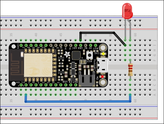
Begin by mounting the LED onto the breadboard. Connect one end of the 220 Ω resistor to the positive leg of the LED (the positive leg of an LED is usually the taller one of the two legs). Connect the other end of the resistor to pin 5 of the ESP8266 board. Then connect the negative leg of the LED to the GND pin of the ESP8266 board. The connection is as shown in the following diagram:

Once the setup is complete, connect the ESP8266 board to your computer via a USB cable...