
Many of the tools in the Part Design workbench will seem familiar from the Draft workbench. The workflow however is quite different. Built around the idea of feature-based design, geometry in the Part Design sketcher is first drawn very roughly and then refined with constraints. As the constraints are added, the built-in solver will adjust the geometry to satisfy the constraint requirements.
In this recipe, we'll design a simple part that has features in two axes and show how it can be revised with constraints. In a later recipe, we'll add features to this part.
Begin with a new, empty document. Switch to the Part Design workbench and click on the button to create a new or edit the selected sketch. A dialog will popup asking which plane you want the sketch oriented on. Select the XZ-Plane option and click on OK.
Roughly draw the end profile of the part. Don't worry about accuracy at this point. The following example was drawn with an arc and a wire:

Add geometric constraints. Constraints are added by selecting the parts of the sketch to be constrained and pressing the appropriate constraint button. A new constraint icon will be added to the drawing and it will be listed in the left-side panel.
Start by adding horizontal and vertical constraints to any crooked lines.
If lines are supposed to connect, select the vertexes and add coincident constraints.
Select pairs of matching lines and add an equality constraint. This forces the lines to be equal length.
When the sketch looks symmetrical, add dimension constraints. Start by constraining the most important dimensions. For instance, we've constrained the radius of the arc to 25 mm.
As you add constraints, watch the solver message at the top of the task panel. As the number of Degrees Of Freedom (DOF) approaches zero you may find it difficult to add constraints without getting a conflicting constraints error. Grabbing a vertex or segment and dragging it can show you where the sketch is still under constrained.
If the sketch gets to 2 DOF and dragging a segment just moves the entire sketch, it's time to lock it. Pick a vertex (we used the center of the arc) and click on the lock button. This will add vertical and horizontal distance constraints which lock the vertex to the origin of the coordinate system. A fully constrained sketch will turn green. Celebrate.

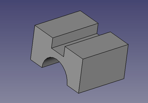
Click on the close button in the task panel. Use the pad tool to pad the sketch to 75 mm and rotate the sketch to see your part.
Even after the sketch has been padded, you can still edit it by double-clicking it in the tree. When saved, your changes will be immediately incorporated into the part.
Constraints limit the ways in which an object can transform. A circle on a plane can be moved in two directions and can have its radius changed. Thus it has three degrees of freedom. When its radius is constrained it has 2 DOF and when its center is locked in X and Y, it is considered fully constrained.
Geometric constraints are those that affect the shape or relationship of entities; horizontal, vertical, tangent, symmetric, and so on.
Dimension constraints have a number. Double-click the constraint to edit the value. Length, radius, and angle are all dimension constraints.
Modeling with constraints is very practical for discrete parts where the features have an implied relationship between them.
Avoiding and eliminating conflicting constraints is the biggest challenge most users face with the sketcher. Practice goes a long way towards improving your skills but following some basic guidelines will also help.
Apply symmetry constraints first. Next apply geometric constraints (horizontal, vertical, tangent, and so on) before dimension constraints (anything with a number).
When possible, fix the horizontal or vertical distance rather than constraining the length.
Try to apply coordinate locks last. In other words, try to get the sketch constrained with itself before you try to constrain it to the coordinate system.
It's generally easier to use several simple sketches to build up the complexity of your part rather than one large sketch with many constraints. Keep your sketches as simple as possible. Whenever possible, use chamfer and fillet operations on the solid rather than modeling the beveled or rounded corners in the sketch.