
Sometimes it is desirable to use geometry that was created in other CAD or modeling programs. FreeCAD can import a wide variety of file types. DXF, STEP, STL, SVG, VRML, Collada, and IDF are just some of the file formats that it can use.
In this recipe, we will open a DXF file and use the geometry in it to form a 3D solid.
You should have a DXF file produced by a CAD program such as QCAD, LibreCAD, Draftsight, or AutoCAD available to produce a DXF file.
In FreeCAD, open the Draft workbench and then select Preferences from the Edit menu.
In the Preferences dialog, click on the Draft icon and then click on the Import/Export tab.
Under DXF format options, change Import style to None (fastest).
Uncheck all the other boxes in that same section. Click on Apply and then OK.

Create some geometry in another CAD program. For this example, we will use DraftSight to create a simple shape. The following is a polyline rectangle with four fillets and a circle:
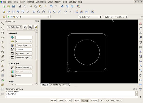
The lines and arcs in this drawing are a polyline. These will translate nicely into FreeCAD and help us create a solid to subtract the circle from.
In FreeCAD, select Import from the File menu.
Select the
dxffile that you want to import.In the Combo View, look at the Project tab and expand the icons.

Switch to the Draft workbench so that we can Upgrade the Circle with the icon that looks like an arrow pointing upward.
Select the geometry labeled as Polyline and use the Part workbench with the Extrude icon to extrude it into a solid.
Extrude the geometry labeled Circle into a solid. Make sure that its height is the same as the solid made from Polyline.
Select the solid that you created from Polyline and then the solid created by Circle.
Use the Boolean Cut operation in Part workbench to subtract the Circle solid from the Polyline solid.

DXF importing relies on code within the Draft workbench, so its settings are controlled from Draft preferences. The dxf polyline imported in as a face that could be extruded in the Part workbench. The Draft workbench has tools for changing other 2D geometry into faces, using the Upgrade tool, which allows the Part workbench to make solids from them. Faces will extrude as solids, whereas a closed shape without a face will just extrude into a thin object that looks like walls.