

Example use case and deployment
The most effective way to understand an IoT and edge computing system is to start with the use case of a real-world product. Here we will study what the solution is intended to deliver and then focus on the underlying technology. Users and customers will not detail full system requirements, and gaps will need to be derived from the constraints. This example will also illustrate that IoT deployments are a cross-domain collaboration between different engineering disciplines and sciences. Often, there will be digital designers, networking engineers, low-level firmware engineers, industrial designers, human factor engineers, board layout electrical engineers, as well as cloud and SaaS developers. However, the design can't be architected in various silos. Often a design choice in one area could lead to poor performance, bad battery life, exorbitant network charges, or unreliable communication to remote devices.
Case study – Telemedicine palliative care
A provider of in-home care and consultation for elderly and senior citizens intends to modernize their current practice of in-home nursing and nursing assistance care with better, more actionable, and economical solutions to address the growing crisis of costs and patient numbers. Currently the service maintains in-home care with 7-day routine visits to over 500 patients within a 100-mile radius of a metro area in Madison, Wisconsin. Visits consist of everything from delivery of medicine and special care services to measurements of patient vitals. Patients are typically over 70 years old and have no ability to administer any IT infrastructure brought into the home. Additionally, patient homes may not have any Internet connectivity or broadband connection.
Requirements
The provider wishes for a system to provide these minimum feature sets and services:
- Each patient will be assigned a wearable device to monitor heart rate, blood oxygen, movement, temperature, and steps taken.
- An additional device(s) will be installed in patient homes to monitor specific patient conditions and vitals such as blood pressure, blood glucose levels, weight, oral temperature, and so on.
- The system must report data on patient vitals to a central operations dashboard.
- The system will also remind patients of events such as when to take a certain pill or when to administer a vital test.
- The system must be able to track status of a patient in the event of power failure.
- A wearable system is provided with an easily identifiable push button that will signal an emergency situation (such as a fall) to the awaiting operator service. The device will flash to indicate an emergency has been activated. The device will have two-way audio communication with the operator. In the event of a hearing-impaired patient situation, an alternative method will be used to communicate to the patient.
- The entire network must be able to manage 500 current patients and grow in scale at 10 percent per year.
- The system must deliver an overall cost savings and ROI of 33 percent within three years of implementation. This key performance indicator (KPI) is measured by reducing in-home nursing and nursing assistance care from three hours per day to two hours per day while increasing the quality of healthcare for patients in the program.
Implementation
Medical IoT and telemedicine are one the most rapidly growing fields of IoT, AI/ML, and sensor systems. With a growth rate year over year (YoY) of 19 percent and a market of $534 billion by 2025, it has garnered much interest. However, we examine this specific case study because of the sizable constraints it places on the system designer. Specifically, in areas of healthcare, the stringent requirements and HIPAA and FDA regulations impose constraints that have to be overcome to build a system that affects patients well-being. For example, HIPAA will require patient data to be secured, so encryption and data security will have to be designed and qualified for the entire system. Additionally, here we examine constraints of the elderly, namely the lack of robust Internet connectivity, while attempting to build an Internet-connected system.
The system will be broken down into three major components:
- The far edge layer: This will consist of two devices. First will be a wearable device for the patient. The second will be a myriad of different medical-grade measurement tools. The wearable will be a wireless device while the other measurement devices may or may not be wireless. Both will establish secured communication to the PAN-LAN layer component described next.
- The near-edge PAN-WAN layer: This will be a secured device installed within the locality of the patient home or where they may be cared for. It should be portable but once installed, it shouldn't be used and tampered with by the patient. This will house the PAN-LAN networking infrastructure equipment. It also contains the edge computing systems to manage the devices, control situational awareness, and securely store patient data in the event of a failure.
- Cloud layer: This will be the aggregation point to store, record and manage patient data. It also presents dashboards and situational awareness rules engines. The clinician will manage a fleet of installed home-care systems through a single dashboard and pane-of-glass. Managing 500 patients with 10 percent growth YoY will present challenges in managing that amount of data quickly especially in emergency situations. Therefore, rules engines will be built to determine when an event or situation exceeds a boundary.
The three layers of the architecture comprise the system from sensor to cloud. The next sections detail aspects of each layer.
The single use case we chose is simply an IoT event from the wearable that must propagate to the cloud for dashboard visibility. The dataflow stretches through all three layers of this IoT use case as shown in the following figure:
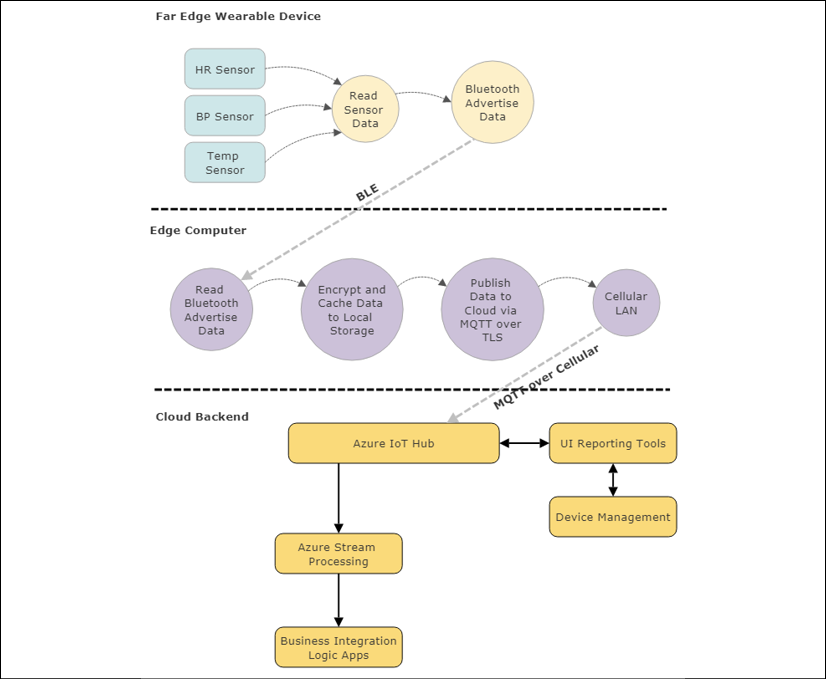
Figure 6: Basic dataflow and software components in this use case example. Note the role of the edge computing device providing translation between a Bluetooth device and the cloud over a transport protocol. It also serves the roles of a caching server and encryption agent.
This use case will read from integrated sensors and broadcast the data as BLE advertised packets as a paired BLE device to the edge computer. The edge system manages the relationship to the Bluetooth PAN and will retrieve, encrypt, and store the incoming data in the event of a power or communication failure to the cloud. The edge system has the additional responsibility of converting the Bluetooth data into TCP/IP packets wrapped in an MQTT transport.
It also must set up, manage, and control a cellular communication with a subscription provider. MQTT allows for the reliable and robust transport to the awaiting cloud system (Azure in this example). There data is encrypted over the wire through TLS and then ingested by the Azure IoT Hub. At that point, data will be authenticated and marshalled through the Stream Analytics engine and to the Logic Apps where cloud-based web services will host a dashboard of patient information and events.
Far edge architecture
Let's begin with the far edge and wearable design. For this project, we start with breaking down the user requirement into actionable system requirements:
| Use case | Choices | Detailed description |
|
Wearable patient monitor |
|
Patient-wearable device. Device should maintain integrity under several environmental parameters such as water submersion, cold, heat, humidity and so on. |
|
Wearable vital monitors |
TI AFE4400 heart rate and pulse oximeter |
Medical-grade heart rate monitor and blood oxygen sensor |
|
ST Micro MIS2DH Medical Grade MEMS Accelerometer |
Movement and pedometer sensor |
|
|
Maxim MAX30205 Human Body Temperature Sensor |
Medical-grade temperature sensor |
|
|
Emergency call button |
A single visible push button with an LED on the unit |
The button should depress but not create false positive events. Additionally, a light should flash when an emergency situation is activated. Additionally, a two-way communication can be initiated. |
|
Edge control system |
ST Micro STM32WB microcontroller |
System to interface sensors and provide PAN communication to PAN-WAN layer. Edge system contains necessary radio hardware and audio codecs. |
|
Microphone |
Knowles SPU0410LR5 audio, microphone and amplifier |
Two-way communication in event of emergency. |
|
Power system |
Encased Li-ion battery in wearable. |
The system should have multi-day rechargeable battery life with warnings to the patient and clinician in event of a low-power state. Power system should be rechargeable or replaceable. |
|
Pairing |
Bluetooth Zigbee Wi-Fi |
Need a method to pair and associate wearable attributes within the home PAN-LAN hub. |
The intent of the wearable device in a palliative care situation is to be reliable, robust, and durable. We chose medical-grade components and environmentally tested electronics to withstand use cases that may arise in home care. The device also will have no serviceable parts. For example, for this use case, we chose not to burden the patient with recharging the wearable as this procedure may not be followed reliably. Since the project still requires in-home nursing and nursing assistance care, part of the task of the nursing assistance will be to recharge and monitor the health of the wearable.
A system usually starts with the constraints of the embodiment of the components. In this case, a wearable system for in-home health care of the elderly could be in the form of a wristband, neck strap, arm strap and so on. This project has chosen a wrist strap akin to a hospital-style name band that a patient would already have some familiarity with. The wrist strap allows for fitting close to the skin and arteries to allow for collection of health characteristics. Other forms of wearables failed to provide more robust contact. The wrist strap does have significant constraints in size, power, and shape that must contain all the electronics, power supply, and radios described in the following.
From a block diagram perspective, the wearable will consist of as few components as possible to minimize space and weight while conserving as much power as possible. Here we elect to use a very power-efficient microcontroller with a Bluetooth 5 radio (Bluetooth Low Energy – BLE). The BLE radio will serve as the PAN communication to the PAN-WAN hub. BLE 5 has a range of up to 100 meters (or further when LE Long-Range Mode is enabled).
This will be sufficient for in-home care situations where the patient will not necessarily leave.
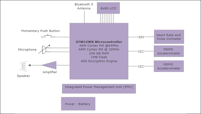
Figure 7: Wearable computing device for in-home palliative care
Edge layer architecture
The PAN-WAN edge layer is the central edge computer, gateway, and router. In many instances this functionality is performed by a smartphone device; however, in this implementation, we need to construct a system using a different and more economical cellular service plan than what is typically offered for smartphone consumers. Because our scale is 500 users and growing, we decide to build a hub using off-the-shelf hardware components to deliver the best solution for the customer.
The edge computer we chose is an industrial-grade single board computer capable of running an enterprise grade distribution of Linux. The Inforce 6560 acts as a gateway between the Bluetooth 5.0 PAN and a cellular WAN. The system on chip (SOC) conveniently incorporates the following hardware:
- Snapdragon 660 processor with a Qualcomm Kryo 260 CPU
- 3 GB of onboard LPDDR4 DRAM
- 32 GB of eMMC storage
- One microSD card interface
- Bluetooth 5.0 radio
- 802.11n/ac Wi-Fi 2.4GHz and 5GHz radio
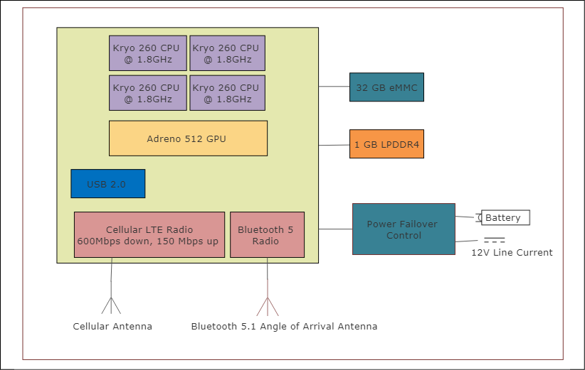
Figure 8: Edge system hardware block diagram
The edge computer will also make use of a Bluetooth 5.1 location-tracking angle-of-arrival antenna array. This new standard will allow the edge system to obtain centimeter precision on the location of the wearable and patient within the Bluetooth field. This will allow for tracking the patient's movement, exercise, bathroom functions, and emergency situations.
The edge relies on a failover power system or uninterruptible power supply (UPS). The UPS device will switch from line current to battery in the event of power removal or power outage. It will signal to the edge system that a power event occurred via a USB or serial UART signal. At that point the edge system will communicate back to the cloud management that a power event occurred, and some action may be necessary.
Software architecture
Along with three layers of communication protocols and hardware, there are three different models of software in this relatively simple system. Rather than belabor this use case example with every nuance of the design, including every fault recovery, device provisioning, security, and system state, we will examine the most common usage of delivering patient health data in real time.
The software structure of the wearable device must be compatible with the hardware we have chosen. This implies we chose tools, operating systems, device drivers, and libraries compatible with the architecture and peripherals we are using. We'll start with the wearable, which has the most stringent requirements of code size, battery life, and performance limitations. Since the STM32WB microcontroller is designed as a dual core, we have essentially two systems to manage: the higher-performance ARM M4 core that will run our specific wearable firmware, and a lower-power M0 core that manages the I/O across Bluetooth. We chose a commercial real-time operating system such as ThreadX by Express Logic to allow for a modern development experience rather than a simple control loop which isn't appropriate for this product. We also want to be able to certify the product for medical-grade usage, which is easier when using commercial off-the-shelf operating systems.
The software structure on the wearable is divided into two processes that host numerous threads to manage the wearable display, the speaker and microphone hardware, I/O to the heartbeat and movement sensors, and the Bluetooth stack. The Bluetooth stack communicates across to the M0 core which manages the hardware layers of the Bluetooth radio.

Figure 9: Wearable system software stack divided between two processing cores for application services and IO communication
The edge computer has more processing resources as it must provide for a full TCP/IP stack, PAN and WAN communication and routing, encryption services, storage services, device provisioning, and failsafe firmware upgrades. For the edge system, we chose a Linux Debian-variant system as it provides more features and services than a tightly embedded RTOS. Coordination with the cloud system and all services on the edge computer or on the wearable are coordinated through the "rules engine." The rules engine could be simple "expert system" using custom logic for this customer or use case. A more robust design may use a standardized framework like Drools. Since each patient may need to have a different set of rules, it makes sense to use a dynamic and fungible rule engine that can be uploaded with different patient directives. This is an autonomous top-level supervisor that periodically captures health data, addresses security issues, releases new firmware updates reliably, manages authentication and security, and handles a significant number of error and failure conditions. The rules engine must be autonomous to satisfy the product requirement of the system working without direct control via the cloud.
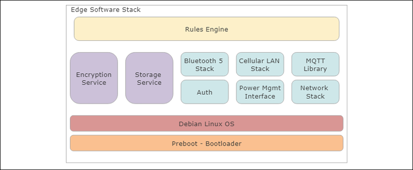
Figure 10: Edge computer software stack consisting of a number of services managed by a single supervising and autonomous "rules engine"
The cloud layer provides the services of ingestion, long-term data storage, stream analytics, and patient-monitoring dashboards. It provides the interface to the healthcare providers to manage hundreds of edge systems securely through a common interface. It also is the method to quickly provide alerts to health situations, error conditions, and system failures, and provide device upgrades securely. The partitioning of cloud services versus edge services are as follows:
- Cloud services
- Data ingestion and management for multiple edge patients and systems
- Almost unlimited storage capacity
- A controlled software deployment and updates to edge
- Edge services
- Low-latency and real-time reactions to events
- PAN communication to sensors
- Minimum connectivity requirements
Commercial cloud services will come with a service agreement and recurring cost, while edge systems for the most part will only incur a single upfront hardware and development cost.
When considering the cloud components, we require a service to ingest data from multiple edge devices securely. The data needs to be stored for analysis and monitoring. The cloud services should also include a method to manage and provision edge installations. Finally, we look for a method to get real-time data from the patients and display it to qualified staff.
For this project, we have chosen to use Microsoft Azure IoT as the cloud provider to manage this large installation and allow for growth and scalability. Azure IoT provides an architecture shown in the following illustration:

Figure 11: Typical Microsoft Azure IoT software stack and cloud architecture
Microsoft Azure IoT software architecture is usually consistent between designs at least on the front end of the IoT Hub. Data will stream from various authenticated sources to the Azure IoT Hub. This is the cloud gateway and capable of scaling to very large IoT installations. Behind the scenes, IoT Hub is a collection of data center processes and services listening and responding to incoming events.
The IoT hub will route qualified streams to the Stream Analytics engine. Here data will quickly be analyzed in real time as fast as data is capable of being ingested. Data can be marshalled to business intelligence services and stored for long persistence in an Azure SQL database and/or moved to a service bus. The service bus responds to events and faults in the form of queues to allow the system to respond to them. The final component in our architecture is the cloud "glue" layers which route data to the IoT device (Logic App Dynamics to Azure) or respond to incoming data (Logic App Azure to Dynamics). Microsoft Dynamics 365 interfaces as a logic app and allows for visibility of IoT events, creation of dashboards, web frameworks, and even mobile and smartphone alerting.
This use case is but a fraction of the actual functionality to make a shipping commercial product. We have left off significant areas such as provisioning, authentication, error conditions, resilient firmware upgrades, system security and root of trust, failover conditions, audio communication, key management, LCD display work, and the dashboard control systems themselves.
Use case retrospective
What we have shown in this very brief introductory use case is that IoT and edge computing requirements for enterprise and commercial designs involve many disciplines, technologies, and considerations. Attempting to trivialize the complexity of bridging Internet connectivity to edge systems with modern expectations of performance, reliability, usability, and security can end in failure.
As we have seen in the abbreviated medical wearable use case, our design involves many interoperable components that comprise a system. It is essential that an architect responsible for an IoT system should be knowledgeable to some level of these system components:
- Hardware design
- Power management and battery design
- Embedded systems design and programming
- Communication systems, radio signaling, protocol usage, and communication economics
- Network stacks and protocols
- Security, provisioning, authentication, and trusted platforms
- Performance analysis and system partitioning
- Cloud management, streaming systems, cloud storage systems, and cloud economics
- Data analytics, data management, and data science
- Middleware and device management
This book is designed to help the architect navigate through the myriad of details and options for each of these levels.