
In this recipe, we will learn how to enable Cisco UCS 6248UP in the FC Switching mode, create FC Zoning on FI, and configure it into Cisco UCS service profile.
Prepare the Cisco UCS 5108 Chassis and install two UCS IOM 2208XP; each UCS IOM is connected to one Cisco UCS 6428UP. Then, configure the two ports on each Cisco UCS 6428UP as an FC Storage port, which is connected to the two FC ports of the SAN Storage controller by Fibre Channel. This SAN storage has two controllers, which in turn has two FC ports. There is one UCS B200M3 installed into this UCS Chassis.
In this recipe, we will learn how to enable the Cisco UCS Fabric Interconnect in FC Switching mode and create Local FC Zoning.
Assume that it has configured the FC port in the UCS Fabric Interconnect.
Follow these steps to enable Cisco Fabric Interconnect in FC Switching mode:
First, log in to the Cisco UCS Manager and identify the FC Mode of the Cisco UCS Fabric Interconnect (FI) in the FC Switching mode. You should change the FC Mode in FC Switching if it is in the End Host, as shown in the following screenshot:

Set the FC Switching Mode to active on the Actions menu of the General tab, as shown:

The Fabric Interconnect will restart after you click on the Yes button and all the ports of the Fabric Interconnect will disconnect:

After the Fabric Interconnect restart is complete, the FC mode displays Switch and Set FC Switching Mode displays in gray. Now the Switch mode of FI is active.

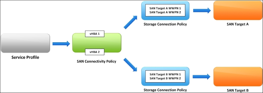
The following diagram describes the concept of local FC Zone on Cisco UCS Fabric Interconnect (FI). It mainly consists of four components, Service Profile, SAN Connectivity Policy, Storage Connection Policy, and SAN Target, as shown in the following screenshot:
Following are the steps to create Local FC Zoning on Cisco UCS Fabric Interconnect:
First, create two Storage Connection Policies:
SAN-TargetAandSAN-TargetB, in Policies on the SAN tab of the UCS Manager. The following table lists the sample configuration for reference:
Storage Connection Policy
Zoning Type
WWPN
Path
VSAN
SAN-TargetA
Single Initiator Single Target
50:06:01:60:47:20:25:EB
A
default(1)
SAN-TargetA
Single Initiator Single Target
50:06:01:61:47:20:25:EB
A
default(1)
SAN-TargetB
Single Initiator Single Target
50:06:01:68:47:20:25:EB
B
default(1)
SAN-TargetB
Single Initiator Single Target
50:06:01:69:47:20:25:EB
B
default(1)
Note
According to the best practices of Fabric Zoning, Single Initiator Single Target option is recommended.
The following screenshot lists the key items required to create the Storage Connection Policy:

After creating two Storage Connection Policies, we can see that it is listed as shown in the following output:

Create one SAN Connectivity Policy
SAN_Con_Policyin the Policies on the SAN tab of the UCS Manager. The following table lists a sample configuration for reference:
Storage Connectivity Policy
vHBA Name
vHBA Initiator Groups
Storage Connection Policy
SAN_Con_Policy
vHBA1
FabA_Zone
SAN-TargetA
vHAB2
FabB_Zone
SAN-TargetB
Assume that vHBA1 is connected to FI-A and vHBA2 is connected to FI-B. The following screen is listed in the key items to create the Storage Connectivity Policy:

After creating the Storage Connectivity Policy named SAN_Con_Policy, it has two vHBA Initiators Groups, FabA_Zone and FabB_Zone. FabA_Zone includes two zones: vHBA1 to SAN-TargetA1 and vHBA1 to SAN-TargetA2. FabB_Zone includes two zones: vHBA2 to SAN-TargetB1 and vHBA2 to SAN-TargetB2.
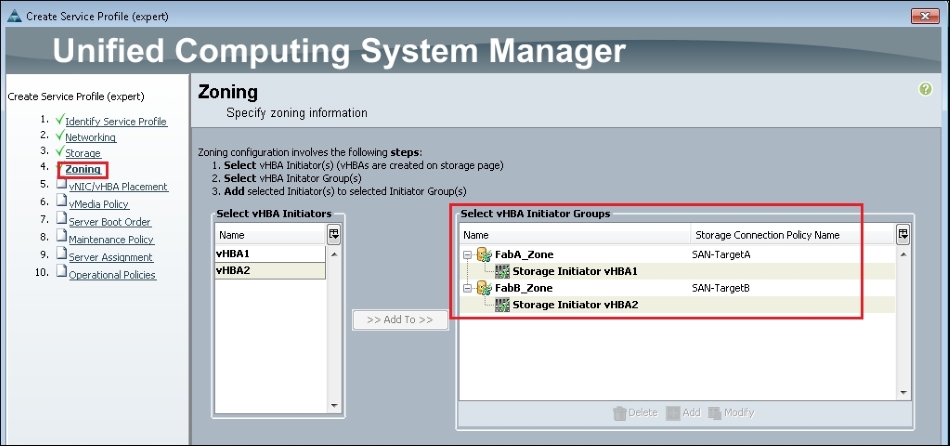
In this recipe, we will learn how to apply the Local FC Zone to the service profile.
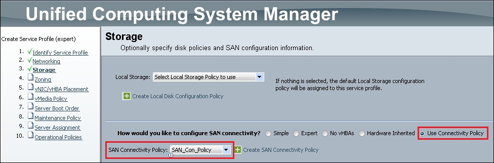
You should choose the SAN connectivity during the creation of a service profile; select Use Connectivity Policy. In the following example, you can select the SAN_Con_Policy, which is defined in the preceding example:
After you select the SAN Connectivity Policy, you can see two vHBA Initiator Groups: FabA_Zone and FabB_Zone, which is defined in the preceding example. This service profile includes four Local FC Zones: