

Device hardware starts with the Printed Circuit Board (PCB), which is comprised of fiberglass, copper, the solder mask, silkscreen, traces, and pads. Components such as resistors, capacitors, chips for Wi-Fi, EEPROMs, and serial and microcontrollers are soldered onto the PCB. There are various layers of thin copper foil that make a PCB conductive and also insulated layers that make it non-conductive. It's important to identify components of interest when looking at a PCB. Components of interest include sources of input into the device firmware either directly or indirectly. Components such as the EEPROM, NAND flash, Universal Asynchronous Receiver/Transmitter (UART), and Joint Test Action Group (JTAG) are some of the most common components to focus on for testing purposes.
This is what a PCB board looks like for a Digital Video Recorder (DVR):
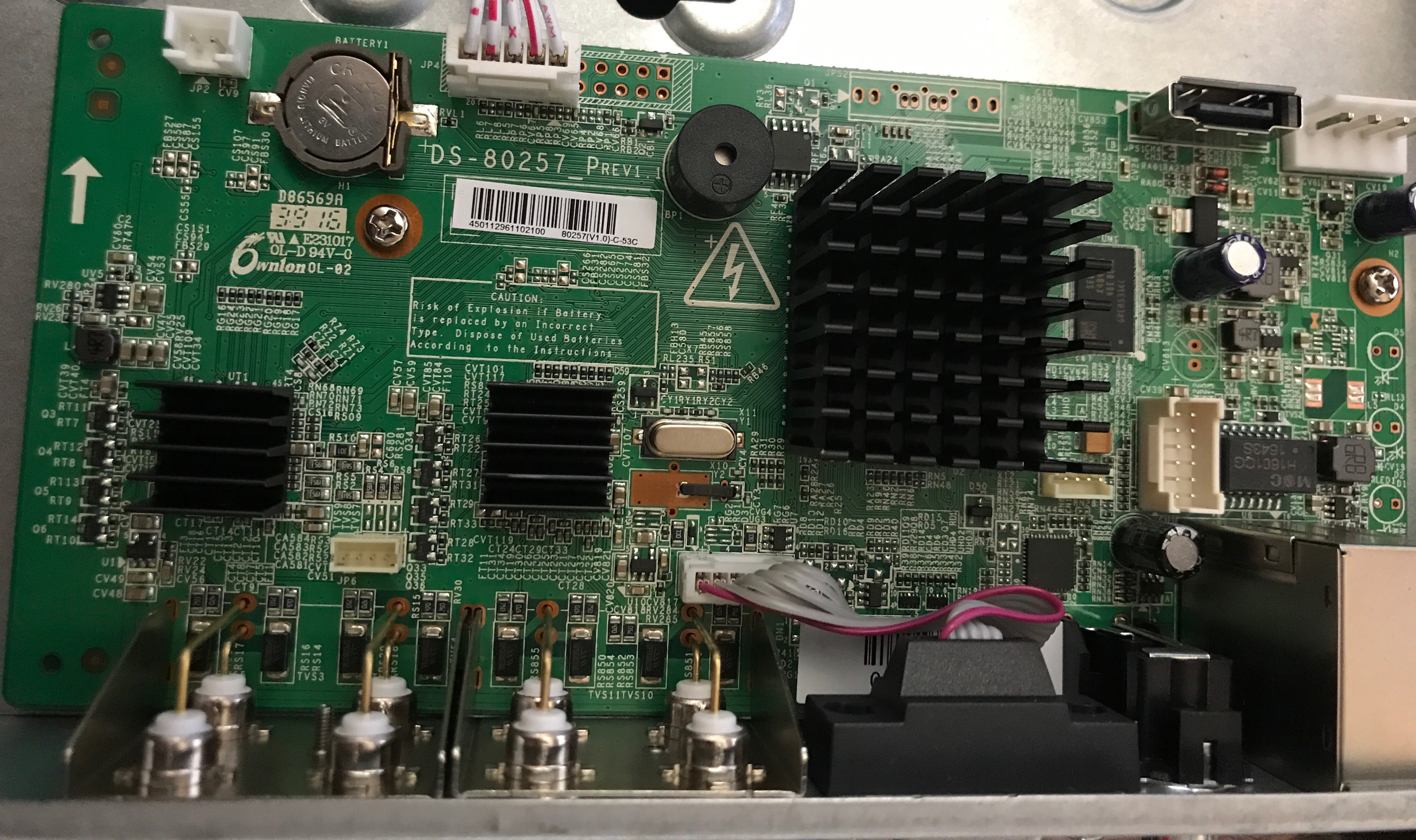
PCB board
The EEPROM is a non-volatile storage location which is read and writable as single blocks of bytes. The EEPROM can be erased by electrical charges or UV exposure. Similar to other flash storage types, EEPROM allows a limited number of write cycles. EEPROM is a chip of interest, as firmware may be loaded on an EEPROM and can be removed from the PCB to an EEPROM reader for further analysis:
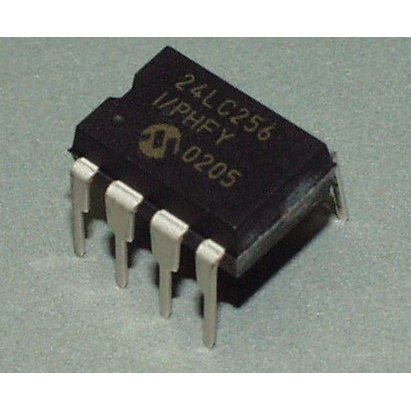
EEPROM Image source: https://cdn.sparkfun.com//assets/parts/3/0/5/EEPROM.jpg
NAND flash memory is written and read in blocks, which are commonly found in USB drives but are also in IoT devices as well as game consoles. The NAND flash typically contains a device's bootloader which follows various instructions to start the operating system and can be manipulated; we will walk you through this later on in this book.
UART is one of the most common ways to gain access to devices. Manufacturers use UART for diagnostics, log messages, and as a debug console for verifying configurations when deploying devices, which makes it one of the most common sources of input in firmware. Since it's used for debugging, root access is commonly granted once connected. However, there are times when UART access is password protected, which may add extra time for brute-forcing. UART contains about eight data lines with control pins and also has two serial wires which are the receive data and transmit data wires (RX/TX). No external clock is needed for UART. UART pinouts on the PCB are TX, RX, Vcc (voltage), and GND (ground). In order to connect to a UART, the TX, RX, and GND must be located using a multimeter. Sometimes, a locating UART may be more difficult on some devices, than others. Some manufacturers may remove the UART header pins from the PCB, requiring soldering to take place. Manufacturers may also cover UART header pins with various layers of silkscreen and cover the headers with another integrated circuit which may be a bit of a pain.
JTAG is another serial communication under IEEE 1149.1. It was created for chip-and system level testing. Manufacturers use JTAG as a source of debugging, similar to UART. There is the ability to password protect JTAG access, but the BYPASS mode should still work. Firmware can be dumped for analysis or upgraded using JTAG. It provides a direct interface to hardware on the board which means it can access devices connected to it, such as flash or RAM. There is a TDI (data in), TDO (data out), TMS (test mode select), TCK (test clock), and TRST (test reset). JTAG connects to an on-chip test access port (TAP) which regulates a state when accessing registers on chips. Similar to UART, manufacturers may obfuscate header pins or traces.
To view the PCB and locate components in an IoT device, one can either disassemble the device or search through third-party sites such as https://fccid.io. An FCC ID is a product ID that is assigned by the FCC in order to keep track of wireless products in the market. Fccid.io is awesome and provides us with loads of detailed information on devices! The FCC publishes various design documents, datasheets, internal images, external images, test reports, various manuals, wireless frequencies, and more. In Chapter 6, IoT Device Hacking, we will walk you through the methodology of hardware hacking to locate hardware details and connect to inputs.