This section explains what Augmented Reality is and the solution provided within the augmentedTi application.
With all technology something and somebody has to be first. Mobile computing and especially smart phones are still in their infancy. Resulting in new technologies, applications, and solutions being devised and applied almost daily.
Augmented Reality is only now becoming viable, as the devices, technology, and coding solutions are more advanced. In this section a coding solution is given, which shows how to implement location-based Augmented Reality. It should work on most smart phones, and can be coded in most frameworks and native code. The code examples given use the Appcelerator Titanium Framework only. No additional modules or plugins are required.
When I was creating an Augmented Reality solution, I spoke to quite a few people, searched the Web, looked at the Appcelerator ArTi example, and came to the conclusion that nobody was giving any real answers on how to implement a usable solution. Everybody was saying the same thing: the key is to minimize processing.
All the examples, tutorials, and documentation I found gave the same solution, which resulted in an interface that was jerky and slow.
The way it worked was quite simple in principal. The Points of Interest (POIs) were all displayed on a single screen as a series of views. These were then moved around the screen depending on the device's location and rotation. The method only showed the POIs currently in view by hiding the others.
This solution, although working, produced the effect of the POIs bouncing in and out. It also meant that every POI had to have actions taken every time the device was moved, resulting in high processing, poor performance, and a jerky interface.
Over the years, computers have become ever more powerful, giving greater processing power and storage capacity. This has produced a generation of programmers, who don't have a real concept of memory and processing management. This is not a criticism; it's just a fact. They haven't had to focus on this, instead just buying more memory.
Mobile devices are different. You have a finite amount of memory and processing power available. To allow for this you need to apply different solutions. Well actually you have to go back to the birth of computing, where programmers had to think about every character they entered into their code. You don't need to minimize the code to this extent, but you will need to apply good coding practices, performance enhancements of code, and techniques to minimize processing and memory usage.
With this in mind, I started to consider how to minimize the processing of the POIs. I know I am not the first to have thought of this solution, but I may be the first to publish it.
My initial thoughts went along the lines of received suggestions; how do you avoid having to process the hidden POIs? Realizing that you would actually have almost as much processing as if you moved them, quickly negated this process.
How do you create a 360 degree panoramic view?
With this thought, I decided that's exactly what you do. You create four views, each one the same size as the device's screen. Each one representing a 90 degree view, placing the POIs on the correct view and then moving the views. This took me from moving 30-50 POIs to moving four views. This solution is generically used when displaying panoramic views of splitting the data into movable chunks.
Placing them in a view which was the width of the screen * 7, meant they could be positioned within that view and moved around easily, using the real estate off the screen, by placing the views outside of the box.
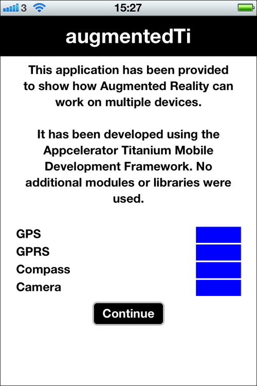
Not all mobile devices are able to run an Augmented Reality application. To ensure the application will work on the device you will need to test for certain sensors, and the camera.
The four tests which are needed to be carried out are for the following:
Within Titanium this is relatively easy, as the framework contains APIs for such purposes. The augmentedTi code base uses four functions within the tools/common.js module. These return true if the sensor is available and active, or false if not.
The controller module calls the functions prior to loading the initial screen. The results are then displayed as blue or red blocks, enabling the application to be controlled as appropriate.
function checkGeoServices(){
    return (Ti.Geolocation.getLocationServicesEnabled)
    ?    true    :    false;}

function checkCompassServices(){
    return Ti.Geolocation.hasCompass;
}

function checkNetworkServices(){
    return (Titanium.Network.online)
    ?    true    :    false;
}

function checkCameraExists(){
    return (Ti.Media.isCameraSupported) ? true : false;
}The key to any location-based application is getting the device's current latitude and longitude. Augmented Reality is no exception.
The Titanium Geolocation API provides the ability to get the current location. For more information on the Titanium APIs refer to the official Appcelerator documentation at http://developer.appcelerator.com/documentation.
Note
They have recently undertaken a major revamp and update of these documents, making for an excellent resource.
Within the services/location.js file you will find all the functions for retrieving the device's current location. There are a couple of gotchas with initially getting the location, it doesn't always update correctly on IOS and used to causes errors on Android, but with Version 2 of Titanium Android has a new location method. To get round this we call the retrieveCurrentPosition function three times from the controller, putting in event handlers to make sure it is only called again when the previous call has finished.
For the location calls we need to set various values, based on the device type:
Ti.Geolocation.headingFilter    =    1;
Ti.Geolocation.showCalibration    =    false;

if(Ti.Platform.osname  ==  'android') {
    Ti.Geolocation.Android.accuracy =
                  Ti.Geolocation.ACCURACY_HIGH;
    Ti.Geolocation.accuracy =
                  Ti.Geolocation.ACCURACY_HIGH;
}
else {
    Ti.Geolocation.distanceFilter    =    10;
    Ti.Geolocation.preferredProvider    =    "gps";
    Ti.Geolocation.accuracy    =
                  Ti.Geolocation.ACCURACY_NEAREST_TEN_METERS;
    Ti.Geolocation.purpose    =
                  Ti.Locale.getString('gps_purpose');
}
We set preferredProvider to gps, which we can do as the device tests make sure that GPS is available and active. Although devices are only accurate to about 5 meters when getting the location, we set the best possible accuracy. The purpose is IOS-specific and is required. You will notice that we are using the localization services functionality in Titanium enabling for the application to be translated.
The main function, retrieveCurrentPosition
, is called by the controller. This function puts the returned location details into persistent data. It uses "try-catch", enabling any errors to be handled gracefully. The controller nextLocationCheck function handles the calls and if the location is obtained successfully, controls the application flow to get the Google Places data. A custom activity indicator, ui/common/activity.js, is shown during this process. The messages are updated showing the current progress of the application.
The Titanium API Ti.Geolocation.getCurrentPosition
, is used to obtain the current location. This is fully documented in the Appcelerator API documentation:
// The controller function
function nextLocationCheck(inParam){
    if(locationCount  <  2) {
        locations.retrieveCurrentPosition();
        locationCount++;
    }
    else {
        var loc    =    persHandler.retPersData({
            type :    0
        });
        var lat    =    persHandler.retPersData({
            type :    1
        });
        var mess    =    'Your current Locations is '  +
                         loc  +  ' ... '  +  lat;
        activity.activityMessage({
            MESS :    mess
        });
        locationCount    =    0;
        retrieveGoogleFeed();
    }
}

// The location function
function retrieveCurrentPosition(){
    try {
        var getLocation =
            Ti.Geolocation.getCurrentPosition(function(e)
        {
            if(!e.success  ||  e.error) {
                common.launchEvent({
                    TYPE :    'ERROR',
                    MESS :    'E0002'
                });
            }
            if(e.success) {
                persHandler.putPersData({
                    type :    0,
                    data :    e.coords.longitude
                });
                persHandler.putPersData({
                    type :    1,
                    data :    e.coords.latitude
                });
                common.launchEvent({
                    TYPE :    'nextLocationCheck'
                });
            }
        });
    }
    catch(err) {
        common.launchEvent({
            TYPE :    'ERROR',
            MESS :    'E0002'
        });
    }
    return;
}
After getting the device's current location, the application moves on to get the Google Places data.
The application uses Google Places data to show the Augmented Reality solution in real time because it is free, well-populated, and world wide. The services/googleFeed.js module retrieves this data and is called from the controller. If you haven't already, you will need to create your own Google Places API key and insert it into the code where indicated. Please see the Installation section.
Google Places returns various data; for a lean application we only process the data we actually need. In your own application, you may have control over the data returned, enabling you to minimize this fully.
Applying the best practices and correct application architecture here is critical to getting a well-performing application. Undertaking too much processing will make the application slow and unresponsive.
In the controller.js file the function that processes the data is processGoogleData. This function loops through each record, calculates the distance and bearing from the device's location, and builds an array of the required data. It then sorts this array based on the distance. The function also updates the activity indicator screen message, and handles any errors gracefully.
If your application requires updates to the data, having built the application flow through the controller, it is simply a case of updating your location by calling the appropriate function, which will handle the remainder of the flow to build the new Augmented Reality display.
There are three values that need to be calculated to be able to display the data in an Augmented Reality view. These are distance, bearing, and degree. Within the application these are calculated in the tools/augmentedReality.js module. A forth value, radius, is required to show the radar blips.
Calculating the distance between two points requires using a calculation, that you probably haven't used since school. There are three formulas commonly available to do this—haversine , Spherical law of Cosines , and Pythagoras theorem . Each has a different level of accuracy and required processing power. The haversine formula is the most accurate but also the most processor intensive.
In the augmentedTi application we use the Spherical law of Cosines formula for a few reasons. The first is that a device is only accurate to 5 meters; this formula is also accurate to about 5 meters. It requires a lot less processing power than the haversine formula. As you develop your own application, you will need to decide which is right for you, accuracy over performance is the main question.
The controller calls a function to calculate the distance passing the current latitude and longitude of the device and the data record received from Google Places. Consider the following:
var currLocation    = {
    lat : persHandler.retPersData({type: 1}),
    lng : persHandler.retPersData({type: 0})
};
var dataLocation    = {
    lat : inParam.DATA.results[i].geometry.location.lat,
    lng : inParam.DATA.results[i].geometry.location.lng
};
var calcDistance =    augmentedReality.calculateDistance
                      (currLocation, dataLocation);
The following calculateDistance function returns the distance between the two points:
function calculateDistance(point1, point2){
    var R    =    6371;
    var d    =    Math.acos(((Math.sin(point1.lat)  *
                  Math.sin(point2.lat))  +
                  (Math.cos(point1.lat)  *
                  Math.cos(point2.lat))  *
                  Math.cos(point2.lng  -  point1.lng)))  *
                  R;
    return d;
}
Not being a mathematician I won't be going into all the details here; suffice to say, it works, quickly and accurately enough for the augmentedTi application.
The bearing is calculated to enable the application to show the POIs and radar blips correctly. It is also used to calculate the degree value, which is also required. The calculations for this have come from the Appcelerator example ARti application. Having already built the required longitude and latitude variables we use these again to pass to the calculateBearing function from the controller:
var calcBearing = augmentedReality.calculateBearing(currLocation, dataLocation);
The calculateBearing function returns the bearing between the two points:
function calculateBearing(point1, point2){
    var lat1 =    point1.lat  *  Math.PI  /  180;
    var lat2 =    point2.lat  *  Math.PI  /  180;
    var dlng =    (point2.lng  -  point1.lng)  *
                  Math.PI  /  180;
    var y    =    Math.sin(dlng)  *  Math.cos(lat2);
    var x    =    Math.cos(lat1)  *  Math.sin(lat2)  -
                  Math.sin(lat1)  *  Math.cos(lat2)  *
                  Math.cos(dlng);
    var brng =    Math.atan2(y, x);
return brng;}The degree is calculated to enable the switch between the bearing and degrees required for displaying the POIs on the correct view. The calculations for this have again come from the Appcelerator ArTi application. To calculate the degree, we pass the previously calculated bearing to the toDegree function from the controller:
var calcDegree = augmentedReality.toDegree(calcBearing);
The toDegree function returns the degree based on the previously calculated bearing:
function toDegree(radius){
    return ((radius * (180 / Math.PI)) + 360) % 360;
}
These values are then added to the array record of the Google Places data, for use during the building of the display.
The radius is calculated by passing the bearing to the toRadius function. The calculation for this has again come from the Appcelerator ArTi application. It is not actually stored anywhere, as it is only required for processing the 2DMatrix, associated with the screen radar and moving the blips.
augmentedReality.toRadius(currBearing)
The toRadius function returns a value calculated from the previously calculated bearing:
function toRadius(degree)
{
    return degree  *  (Math.PI  /  180);
}
That is all the heavy maths. We use more while building and moving the Augmented Reality display, but they are built into the display function, which is explained shortly.
After the calculations have been performed and the data processed, we end up with an array that contains records with multiple elements:
googleData.push({
      id :    inParam.DATA.results[i].id,
      icon :    inParam.DATA.results[i].icon,
      name :    inParam.DATA.results[i].name,
      location :    dataLocation,
      distance :    calcDistance,
      bearing :    calcBearing,
      degree :    calcDegree,
      vicinity :    inParam.DATA.results[i].vicinity});
This keeps the amount of data to be passed to a minimum. The final task to perform on the data is to sort it by distance. We do this to enable the correct display of the data. During the building of the interface we process the array record by record. If we didn't sort this by distance we would have POIs that are further away on top of closer POIs. When we scale the size of the POIs while building the interface, this order of the data is essential. It avoids having to use any special calculations to work out the zIndex, adding to processing.
googleData.sort(function(aa, bb)
        {
            return aa.distance  -  bb.distance;
        });
googleData.reverse();This section will go into the details of how to build the multi-view display, place the POIs on the correct view, build the radar, and display the blips.
Although this book and the example application try to show a good coding practice, for the purposes of the augmentedTi example application, I have used just one module, which incorporates the whole Augmented Reality display and movement. This could easily be split into multiple modules (and may well be in the future). This module is just over 600 lines long including comments, so it is not too excessive.
The ui/screens/ARScreen.js module contains the whole interface code. Now we need to see how it builds and moves the interface. When this module is called, it initially creates the new window and displays the activity indicator, making sure the user knows something is happening. It then starts to build the overlay in the buildAROverlay function.
The buildAROverlay function controls building the Augmented Reality view, which consists of the main view, the radar image, the Close button, the required Google logo, the display of the POIs, and opening the camera. Most of these are controlled by separate functions. Each specific section of the build is covered in the following subsections.
The radar is an image placed just below the top right of the screen. Its purpose is to indicate where POIs are in relation to the current direction of the device. It works by drawing blips or in this case a small view with a background color and radius to give a circle, on the image in the correct place. This is done by using the distance of the POIs from the current location and their compass bearing. We have already calculated these values in the previous sections, so we just need to apply them.
Within the augmentedTi example Augmented Reality application the Radar image is located in the images directory and called radar.png
. This is an open source image found on the Web, so if you need to use it you can:

Note
To get get the correct radar display and movement, it is vital you know the exact size of the display area. I resolved this by having no white space around the image at all. You will also need to make the background transparent.
The radar itself is made up of two views. The first is arRadarBck
, which is used to set the base image of the radar. The second, arRadarImg
is used to hold the blips and rotate as the device is moved; it has a transparent background. Setting the zIndex guarantees that the views appear in the right layer.
The blips are generated at the same time as the POIs, to save processing the data more than once. These are built at the end of the buildARData function.
var ro      = ((images.file.radar.wCalc)  *
              (googleData[iPos].distance.toFixed(4)  /
              1000)  /  2);
var centerX = ((images.file.radar.wCalc)  /  2)  +
              (ro  *  Math.sin(googleData[iPos].bearing));
var centerY = ((images.file.radar.wCalc)  /  2)  -  (ro  *
              Math.cos(googleData[iPos].bearing));
var displayBlip  =  Ti.UI.createView({
      height :    layout.css.ar.blip.height,
      width :    layout.css.ar.blip.width,
      backgroundColor :    layout.css.ar.blip.color,
      borderRadius :    2,
      top :    centerY  -  1,
      left :    centerX  -  1,
      lat :    googleData[iPos].location.lat,
      lng :    googleData[iPos].location.lng
});
arRadarImg.add(displayBlip);
You will see from the code that we calculate the position using the Distance, Bearing, Image Width and what appears to be a random figure of 1000. This figure is actually worked out to fit the blips onto the radar image correctly, as the distance is in kilometers. The blip is created as a view with borderRadius
and backgroudColor
, making a nice circle.
These calculations work nicely and again, I am not a mathematician—trying to explain all the math could result in providing you with misinformation.
To display the Google Places data, or as is normally referred to as POIs, we need to build four views which will sit next to each other in a parent view and contain the POIs for the correct bearing. The buildARDisplay function creates these containers. The initial container is created seven times the screen's width and placed centrally. This gives a view which has most of it outside of the screen area. This is used to display the other four views and enable them to be easily moved around.
var poiDisplay =    Ti.UI.createView({
        top    :    0,
        height :    screenHeight,
        left   :    0  -  (screenWidth  *  3),
        width  :    (screenWidth  *  7),
        backgroundColor :    'transparent',
        zIndex :    50
    });
The other four views, of the same size as the screen, are then created and added to this parent view before the parent view is added to the overlay. Each of the four views is positioned by its right parameter. This has to be done because moving the views around, we set the right position within the parent view. If we used the left positioning, as the device is rotated, the views would move in the opposite direction to that required.
poiView1    =    Ti.UI.createView({
        top    :    0,
        height :    screenHeight,
        right  :    0,
        width  :    screenWidth
    });
The right positioning is set at 0 for view 1, set at the screen width for view 2, set at twice the screen width for view 3, and 0 - the screen width for view 4.
The views are then populated with the Google Data, each view representing 90 degrees of the compass. The buildARData function, which we have already seen in the radar, is used to calculate which view a POI is displayed in. Each POI has a scale applied to it to reduce its full size down depending on the distance it is away from the device's location. As previously mentioned, the data has been sorted by distance enabling the data to be processed farthest to nearest:
var scale = (10 / googleData[iPos].distance).toFixed(2);
if(scale  >=  1) {
    scale    =    1.00;
}
if(scale  <=  0.35) {
    scale    =    0.35;
}
After the scale has been calculated the POIs degree
value is used to select the view it is to be displayed in, calculating the left and top positions. It is built and added to that view.
Note
For the augmentedTi example application the Google Places icon is displayed. This keeps the data on the screen to a minimum.
In calculating the position in the view of the POI we divide the screen width by 90, and multiply it by the degree to get its exact position.
To make the application do something after the POI view has been created, the addPOIEvent function is called. This function adds an event listener to the image, allowing it to be pressed and display some more data on the screen.
Note
It is worth noting that adding event listeners within a for loop is not good practice, which is why it has been separated out into its own function.
The four views each deal with 90 degrees of the compass. View 1 has the POIs which are between 315 and 45 degrees. This is done as we require this view to be positioned "right 0" on the screen when the compass is pointing at 0 degrees. Using this as the base, the remaining views deal with the next subsequent 90 degrees, as the following code snippet shows:
var tmpDegCal    =    0;
var tmpView    =    null;
if(googleData[iPos].degree  <=  45  ||
   googleData[iPos].degree  >=  315) {
      tmpDegCal    =    -45;
      tmpView    =    poiView1;
}
else if(googleData[iPos].degree  <=  135) {
      tmpDegCal    =    45;
      tmpView    =    poiView2;
}
else if(googleData[iPos].degree  <=  225) {
      tmpDegCal    =    135;
      tmpView    =    poiView3;
}
else {
      tmpDegCal    =    225;
      tmpView    =    poiView4;
}
var tmpLeft = ((googleData[iPos].degree  -
              tmpDegCal)  *  (screenWidth  /  90))
              - ((layout.css.ar.detail.ics * scale) / 2);
var tmpTop    =    (screenHeight / 2)  *  scale;

if ((tmpLeft + ((layout.css.ar.detail.ics * scale / 2))) >=
     screenWidth){
       tmpLeft = screenWidth - (layout.css.ar.detail.ics *
        scale);
}
if (tmpLeft <= 0){
     tmpLeft = 0;
}
var poiItem    =    Ti.UI.createImageView({
    height :    layout.css.ar.detail.ics  *  scale,
    width :    layout.css.ar.detail.ics  *  scale,
    left :    tmpLeft,
    top :    tmpTop,
    image :    googleData[iPos].icon
});
addPOIEvent({
    VIEW :    poiItem,
    POS :    iPos
});
tmpView.add(poiItem);
tmpView    =    null;
Note
This code does not deal with height, but how to apply this functionality is explained in the Updating the Data section.
We now have all the data built within the application and can move on to displaying it as an overlay on the camera and making it move.
Within Titanium there are a few APIs for the media services of the device. These give straightforward ways of playing music, videos, or accessing the camera. For an Augmented Reality application, using the Ti.Media.ShowCamera API enables us to display a view through the camera, remove all the controls, and overlay our Augmented Reality data. The augmentedTi example application uses this; as we have already tested for the camera, we can either display the camera view or just add the Augmented Reality onto the window's base view.
if(cameraView) {
  Ti.Media.showCamera({
    success : function(event){},
    cancel : function(){},
    error : function(error){
    if(error.code  ==  Ti.Media.NO_CAMERA) {
      common.launchEvent({
        TYPE :    'ERROR',
        MESS :    'E0006'
      });
    }
    else {
      common.launchEvent({
        TYPE :    'ERROR',
        MESS :    'E0006'
      });
    }},
    mediaTypes :    [Ti.Media.MEDIA_TYPE_VIDEO,
                     Ti.Media.MEDIA_TYPE_PHOTO],
    showControls :    false,
    autohide :    false,
    autofocus :    "off",
    animated :    false,
    overlay :    arBaseView
  });
}
else {
  arWin.add(arBaseView);
}
This will display all the data onto the screen and make it ready to be moved around.
When the application goes into the background or the Close button is pressed, the camera view is removed by passing control back to the controller, and running the resetVars function that firstly runs Ti.Media.hideCamera(). It then resets the application variables, enabling the initial screen to be displayed with all the previous set values and data removed.
We have now hit upon the key part of Augmented Reality: making everything move as the device is rotated. Up until now we have been dealing with getting the location and data, formatting this into a usable and functional display.
Note
Although the method of displaying the POIs is crucial to the success of the application, it is not quite as important as getting the movement right.
As we have already seen, most Augmented Reality implementations use a very different approach to the solution in this book. If we had written the normal solution I would now be explaining how to minimize the movement of 20 - 50 POIs and only access the ones currently in view. But we didn't. We created four views and positioned the POIs in these, making the movement of the views straightforward.
We start by activating the Compass
and setting its "heading change" event to 1 degree. For this we return to the services/location.js module. Again it is all controlled by the Ti.Geolocation API:
Ti.Geolocation.headingFilter    =    1;
Ti.Geolocation.showCalibration    =    false;
We have an initial function, retrieveCurrentDirection, which gets the initial compass magnetic heading. Using try-catch enables us to handle errors gracefully. The headingCallback function is fired when the Compass Sensor
is updated by 1 degree. This is triggered by the heading event listener, which is added in its own function:
function retrieveCurrentDirection(){
    var geoLocFuncVar =
        Ti.Geolocation.getCurrentHeading(function(e){
        if(e.error) {
            common.launchEvent({
                TYPE :    'ERROR',
                MESS :    'E0005'
            });
        }
        try {
            addDirectionHandlerLocal();
        }
        catch(err) {
            common.launchEvent({
                TYPE :    'ERROR',
                MESS :    'E0005'
            });
        }
        persHandler.putPersData({
            type :    4,
            data :    e.heading.magneticHeading
        });
    });
}
function headingCallback(e){
    if(e.error) {
        common.launchEvent({
            TYPE :    'ERROR',
            MESS :    'E0005'
        });
    }
    else {
        persHandler.putPersData({
            type :    4,
            data :    e.heading.magneticHeading
        });
        common.launchEvent({
            TYPE :    'rotateDisplay'
        });
    }
}
The gotcha with the compass is on the event listener. If we try to add it when it is already active, it can produce weird results. Trying to remove it when it isn't added can crash the application. Also, if we leave it active when the application closes or goes into the background, it uses up the device's resources and re-opening the app can cause it to crash.
We can resolve these issues with two other functions—one which adds the event listener and one which removes it. We have a module variable set to make sure we only add or remove it where required.
function removeDirectionHandlerLocal(){
    if(compassEventSet) {
        Ti.Geolocation.removeEventListener('heading',
        headingCallback);
        compassEventSet    =    false;
    }
}
function addDirectionHandlerLocal(){
    if(!compassEventSet) {
        Ti.Geolocation.addEventListener('heading',
        headingCallback);
        compassEventSet    =    true;
    }
}
The function to add the event listener is called from the retrieveCurrentHeading function, which is called from the controller. To make sure that we do not leave the event listener functioning, when the Augmented Reality view or the application is closed then the controller calls the removeDirectionHandler function and if the event handler is active it removes it.
Having the compass updating via the heading event, we now need to move the display. This is done by using the rotateDisplay function within ARScreen.js, which is called from controller, and triggered by the compass heading event.
rotateDisplay
receives the bearing and checks to see what it is. It calculates the position of the primary view displayed on the screen and positions the other views relative to this, using a flag that is set at the start of the movement and unset at the end.
This makes sure that the movement is only occurring at a single time. You will see that we use the current bearing minus the bearing offset multiplied by the screen width, which is divided by 90 to calculate the right position of the main view. Also, the main view is different depending on the current bearing.
Note
It may seem straightforward, but it is critical that this is applied correctly. This short piece of code is the whole key to making the Augmented Reality application function.
Before removing the flag, we rotate the blips on the radar, by applying a 2DMatrix
to the view, which contains the blips. The reason we have the view on the radar containing the blips is purely because if we added the blips to the view containing the radar image, the whole image would be rotated, which is not what is required. This is where we use the toRadius function to calculate the rotation required.
function rotateDisplay(){
  if(!rotateFlag) {
    rotateFlag = true;
    var currBearing = parseInt(persHandler.retPersData({
                      type :    4
                      }), 10);
    if(currBearing  <=  90) {
      poiView1.right = ((currBearing  -  0)  *
      (screenWidth  /  90))  +  (screenWidth  *  3);
      poiView2.right = poiView1.right  -  screenWidth;
      poiView3.right = poiView2.right  -  screenWidth;
      poiView4.right = poiView1.right  +  screenWidth;
    }
    else if(currBearing  <=  180) {
      poiView2.right = ((currBearing  -  90)  *
      (screenWidth  /  90))  +  (screenWidth  *  3);
      poiView3.right = poiView2.right  -  screenWidth;
      poiView4.right = poiView3.right  -  screenWidth;
      poiView1.right = poiView2.right  +  screenWidth;
    }
    else if(currBearing  <=  270) {
      poiView3.right    =    ((currBearing  -  180)  *
      (screenWidth  /  90))  +  (screenWidth  *  3);
      poiView4.right = poiView3.right  -  screenWidth;
      poiView1.right = poiView4.right  -  screenWidth;
      poiView2.right = poiView3.right  +  screenWidth;
    }
    else {
      poiView4.right    =    ((currBearing  -  270)  *
      (screenWidth  /  90))  +  (screenWidth  *  3);
      poiView1.right = poiView4.right  -  screenWidth;
      poiView2.right = poiView1.right  -  screenWidth;
      poiView3.right = poiView4.right  +  screenWidth;
    }
    arRadarImg.transform = Ti.UI.create2DMatrix().rotate(-
augmentedReality.toDegree(augmentedReality.toRadius(currBearing)));

    removeFlag();
  }
}
These were the key details of how the augmentedTi example Augmented Reality application was built, giving the details of the solution applied. The scope of the requirements of this project have now been met, but there are a couple of items worth covering, which you will probably need. These are covered in the following sections and explain how to update the data as the device moves. I am sure that in the near future the open source code will be updated to include these items.
Up to now we have seen how to create what I like to term A Single Plain of Existence, which is where the data remains static and moves across the screen, without consideration for the location movement of the device or the tilt. This section covers how to implement the height, distance, and data to the code base.
Having POIs at different heights enables an interesting user experience as you can set a POI on the top of a building or directly on the ground, making the user tilt their device to show the information. To accomplish this, the data for the application needs to have a height value. Currently, Google Places doesn't have this value, which is why it isn't included here.
When you have a height value you can manipulate the tilt movement of the device by using the Ti.Accelerometer API. This gives you the ability to find the tilt and adjust the four views, by increasing their initial height to what you require. As an example you can double the height, making the bottom 0 feet and the top 50 feet. Then each view would be able to be adjusted on the screen within the move section by the current accelerometer value.
As the device moves closer to a POI, it is nice to give the illusion that the POI is getting closer. To achieve this effect a new function to update the location is required. This would listen for a location update and do something when the device has moved say, by 10 meters.
For this you would set the Ti.Geolocation.distance parameter and add a location event listener, creating a locationCallBack function, which triggers another function that resizes the POIs based on distance. The method to resize the POIs is the same as the one used to size them originally.
The gotcha though is that you have to loop through all the POIs view components, calculate the distance based on the new coordinates, and resize the height and width given the new scale, on the original image size.
Note
Run this only as a single instance and not when the view movement is occurring. Make sure that you have a flag set to only allow it to be run in this manner.
When this is done, consideration also needs to be made for the POIs suddenly being behind the device instead of in front. This means that the process of updating the POIs across views needs to be applied.
The augmentedTi example application only updates the Google Places data when you go back to the initial screen. It is quite an easy task to update the data every 100 meters, by applying the location event listener and having a count to 10. When updating the data, you would want to put the activity indicator on the screen and remove the event listeners until the data is fully updated. This is effectively the same as going back to the initial screen and starting the process from getting the data.
Another method could be to build a second set of four views with the new data on and then replace the original views with these. It would negate the need to show the user that the application is processing new data and enable a smooth transition.
If you have followed everything mentioned till now, you should now have an application on your device whose opening screen looks as follows: