

In this book, we will also introduce a camera project. This device will use an infrared camera that will be published in the network, and it will be used by the controller to take pictures when the alarm goes off.
For our camera project, we've chosen to use the LinkSprite JPEG infrared color camera instead of the normal Raspberry Camera module or a normal UVC camera. It allows us to take photos during the night and leaves us with two USB slots free for Wi-Fi and keyboard. You can take a look at the essential information about the camera by visiting http://www.linksprite.com/upload/file/1291522825.pdf. Here is a summary of the circuit connections:
The camera has a serial interface that we can use through the UART available on Raspberry Pi. It has four pins, two of which are reception pin (RX) and transmission pin (TX) and the other two are connected to 5 V and ground GND respectively.
The RX and TX on the Raspberry Pi pin header are connected to the TX and RX on the camera, respectively. In parallel, we connect the TX and RX lines to a logical inverter. Then, via 240 Ω resistors, we connect them to two LEDs, yellow for TX and green for RX, and then to GND. Since TX and RX are normally high and are drawn low during communication, we need to invert the signals so that the LEDs remain unlit when there is no communication and they blink when communication is happening.
We also connect four GPIO pins (18, 23, 24, and 25) via 160 Ω resistors to four LEDs and ground to signal the different states in our application. GPIO 18 controls a green LED signal when the camera application is running. GPIO 23 and 24 control yellow LEDs; the first GPIO controls the LED when communication with the camera is being performed, and the second controls the LED when a network request is being handled. GPIO 25 controls a red LED, and it is used to show whether an error has occurred somewhere.
This project can be better understood with the following circuit diagram:
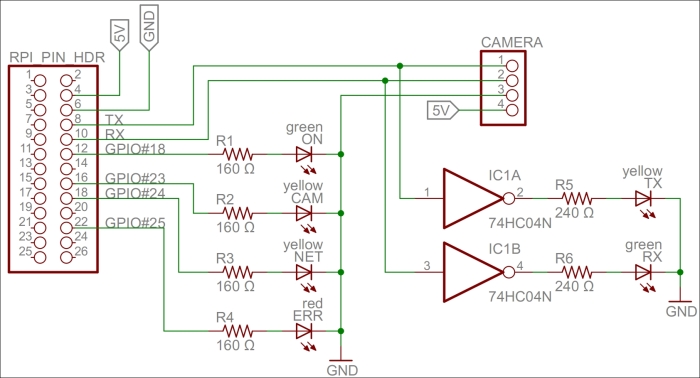
A circuit diagram for the camera project
To be able to access the serial port on Raspberry Pi from the code, we must first make sure that the Linux operating system does not use it for other purposes. The serial port is called ttyAMA0 in the operating system, and we need to remove references to it from two operating system files: /boot/cmdline.txt and /etc/inittab. This will disable access to the Raspberry Pi console via the serial port. But we will still be able to access it using SSH or a USB keyboard. From a command prompt, you can edit the first file as follows:
$ sudo nano /boot/cmdline.txt
You need to edit the second file as well, as follows:
$ sudo nano /etc/inittab
Tip
For more detailed information, refer to the http://elinux.org/RPi_Serial_Connection#Preventing_Linux_using_the_serial_port article and read the section on how to prevent Linux from using the serial port.
To interface the hardware laid out on our prototype board, we will use the Clayster.Library.RaspberryPi library. We control the LEDs using DigitalOutput objects:
private static DigitalOutput executionLed = new DigitalOutput (18, true);
private static DigitalOutput cameraLed = new DigitalOutput (23, false);
private static DigitalOutput networkLed = new DigitalOutput (24, false);
private static DigitalOutput errorLed = new DigitalOutput (25, false);
The LinkSprite camera is controlled by the LinkSpriteJpegColorCamera class in the Clayster.Library.RaspberryPi.Devices.Cameras subnamespace. It uses the Uart class to perform serial communication. Both these classes are available in the downloadable source code:
private static LinkSpriteJpegColorCamera camera = new LinkSpriteJpegColorCamera (LinkSpriteJpegColorCamera.BaudRate.Baud__38400);
For our camera to work, we need four persistent and configurable default settings: camera resolution, compression level, image encoding, and an identity for our device. To achieve this, we create a DefaultSettings class that we can persist in the object database:
public class DefaultSettings : DBObject
{
  private LinkSpriteJpegColorCamera.ImageSize resolution = LinkSpriteJpegColorCamera.ImageSize._320x240;
  private byte compressionLevel = 0x36;
  private string imageEncoding = "image/jpeg";
  private string udn = Guid.NewGuid().ToString();

  public DefaultSettings() : base(MainClass.db)
  {
}We publish the camera resolution property as follows. The three possible enumeration values are: ImageSize_160x120, ImageSize_320x240, and ImageSize_640x480. These correspond to the three different resolutions supported by the camera:
[DBDefault (LinkSpriteJpegColorCamera.ImageSize._320x240)]
public LinkSpriteJpegColorCamera.ImageSize Resolution
{
  get
  {
    return this.resolution;
  }
  set
  {
    if (this.resolution != value)
    {
      this.resolution = value;
      this.Modified = true;
    }
  }
}
We publish the compression-level property in a similar manner.
Internally, the camera only supports JPEG-encoding of the pictures that are taken. But in our project, we will add software support for PNG and BMP compression as well. To make things simple and extensible, we choose to store the image-encoding method as a string containing the Internet media type of the encoding scheme implied:
[DBShortStringClipped (false)]
[DBDefault ("image/jpeg")]
public string ImageEncoding
{
  get
  {
    return this.imageEncoding;
  }
  set
  {
    if(this.imageEncoding != value)
    {
      this.imageEncoding = value;
      this.Modified = true;
    }
  }
}We add a method to load any persisted settings from the object database:
  public static DefaultSettings LoadSettings()
  {
    return MainClass.db.FindObjects <DefaultSettings>().GetEarliestCreatedDeleteOthers();
  }
}
In our main application, we create a variable to hold our default settings. We make sure to define it as internal using the internal access specifier so that we can access it from other classes in our project:
internal static DefaultSettings defaultSettings;
During application initialization, we load any default settings available from previous executions of the application. If none are found, the default settings are created and initiated to the default values of the corresponding properties, including a new GUID identifying the device instance in the UDN property the UDN property:
defaultSettings = DefaultSettings.LoadSettings();
if(defaultSettings == null)
{
  defaultSettings = new DefaultSettings();
  defaultSettings.SaveNew();
}To avoid having to reconfigure the camera every time a picture is to be taken, something that is time-consuming, we need to remember what the current settings are and avoid reconfiguring the camera unless new properties are used. These current settings do not need to be persisted since we can reinitialize the camera every time the application is restarted. We declare our current settings parameters as follows:
private static LinkSpriteJpegColorCamera.ImageSize currentResolution;
private static byte currentCompressionRatio;
During application initialization, we need to initialize the camera. First, we get the default settings as follows:
Log.Information("Initializing camera.");
try
{
  currentResolution = defaultSettings.Resolution;
  currentCompressionRatio = defaultSettings.CompressionLevel;
Here, we need to reset the camera and set the default image resolution. After changing the resolution, a new reset of the camera is required. All of this is done on the camera's default baud rate, which is 38,400 baud:
try
{
  camera.Reset();// First try @ 38400 baud
  camera.SetImageSize(currentResolution);
  camera.Reset();
Since image transfer is slow, we then try to set the highest baud rate supported by the camera:
camera.SetBaudRate (LinkSpriteJpegColorCamera.BaudRate.Baud_115200);
camera.Dispose();
camera = new LinkSpriteJpegColorCamera (LinkSpriteJpegColorCamera.BaudRate.Baud_115200);
If the preceding procedure fails, an exception will be thrown. The most probable cause for this to fail, if the hardware is working correctly, is that the application has been restarted and the camera is already working at 115,200 baud. This will be the case during development, for instance. In this case, we simply set the camera to 115,200 baud and continue. Here is room for improved error handling, and trying out different options to recover from more complex error conditions and synchronize the current states with the states of the camera:
}
catch(Exception) // If already at 115200 baud.
{
  camera.Dispose ();
  camera = new LinkSpriteJpegColorCamera (LinkSpriteJpegColorCamera.BaudRate.Baud_115200);
We then set the camera compression rate as follows:
}finally
{
  camera.SetCompressionRatio(currentCompressionRatio);
}
If this fails, we log the error to the event log and light our error LED to inform the end user that there is a failure:
}catch(Exception ex)
{
  Log.Exception(ex);
  errorLed.High();
  camera = null;
}