-
Book Overview & Buying
-
Table Of Contents

Mastering Palo Alto Networks - Second Edition
By :
Mastering Palo Alto Networks
By:
Overview of this book
Palo Alto Networks’ integrated platform makes it easy to manage network and cloud security along with endpoint protection and a wide range of security services.
This book is an end-to-end guide to configure firewalls and deploy them in your network infrastructure. You will see how to quickly set up, configure and understand the technology, and troubleshoot any issues that may occur. This book will serve as your go-to reference for everything from setting up to troubleshooting complex issues. You will learn your way around the web interface and command-line structure, understand how the technology works so you can confidently predict the expected behavior, and successfully troubleshoot any anomalies you may encounter. Finally, you will see how to deploy firewalls in a cloud environment, and special or unique considerations when setting them to protect resources.
By the end of this book, for your configuration setup you will instinctively know how to approach challenges, find the resources you need, and solve most issues efficiently.
Table of Contents (18 chapters)
Preface

Understanding the Core Technologies
 Free Chapter
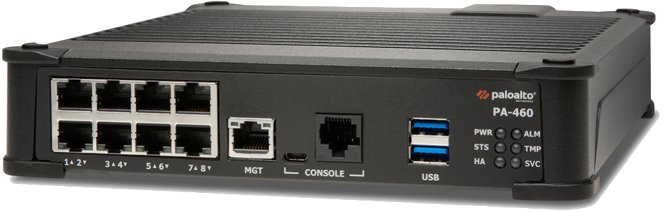
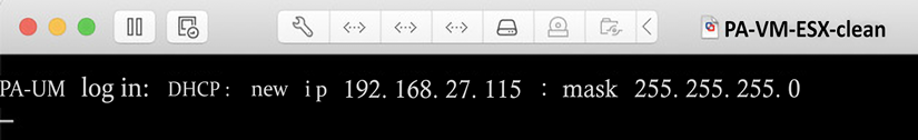
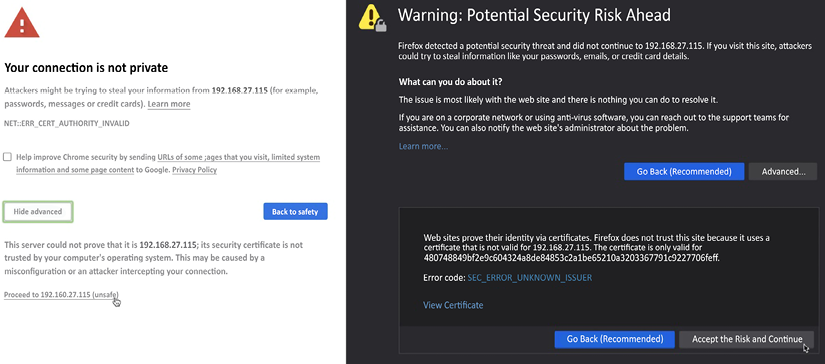
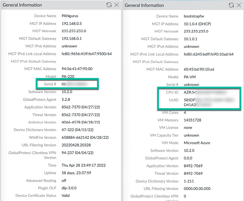
Setting Up a New Device
Building Strong Policies
Taking Control of Sessions
Services and Operational Modes
Identifying Users and Controlling Access
Managing Firewalls through Panorama
Upgrading Firewalls and Panorama
Logging and Reporting
Virtual Private Networks
Advanced Protection
Troubleshooting Common Session Issues
A Deep Dive into Troubleshooting
Cloud-Based Firewall Deployment
Supporting Tools
Other Books You May Enjoy
Index