
Computer science often focuses on subdividing a problem into smaller, hopefully independent components that can be solved in isolation. Once that is done, all that is needed is a set of rules on how those components should communicate to have a solution to the larger problem. This set of rules, along with a pre-agreed data format, is called a protocol. A network is composed of a number of layers, each of which has a fixed purpose. Thus, each of these layers run one or many protocols, forming a stack of protocols. In the early days of networking, different people implemented their networks in different ways. When the internet was conceived, there was a need to make these networks communicate seamlessly. Since they were constructed differently, this turned out to be difficult.
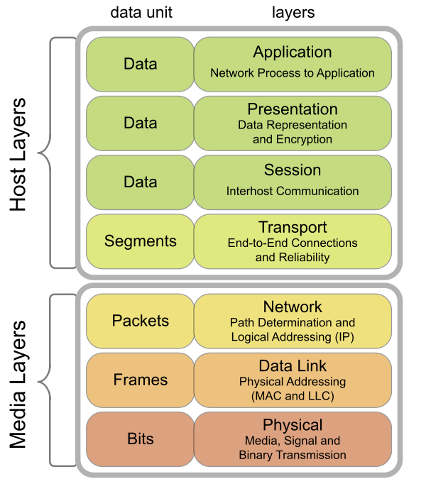
There was a clear need to agree on standard protocols and interfaces to make the internet work. The first attempt at standardizing networking protocols was in 1977, which led to the OSI model. This model has the following layers:
- Physical layer: It defines how data is transmitted in the physical medium in terms of its electrical and physical characteristics. This can either be by wire, fiber optic, or a wireless medium.
- Data link layer: It defines how data is transmitted between two nodes connected by a physical medium. This layer deals with prioritization between multiple parties trying to access the wire simultaneously. Another important function of this layer is to include some redundancy in the transmitted bits to minimize errors during transmission. This is referred to as coding.
- Network layer: It defines how packets (made up of multiple units of data) are transmitted between networks. Thus, this layer needs to define how to identify hosts and networks uniquely.
- Transport layer: It defines mechanisms to reliably deliver variable length messages to hosts (in the same or different networks). This layer defines a stream of packets that the receiver can then listen to.
- Session layer: It defines how applications running on hosts should communicate. This layer needs to differentiate between applications running on the same host and deliver packets to them.
- Presentation layer: It defines common formats for data representation so that different applications can interlink seamlessly. In some cases, this layer also takes care of security.
- Application layer: It defines how user-centric applications should send and receive data. An example is the web browser (a user-centric application) using HTTP (an application layer protocol) to talk to a web server.
The following figure shows a visual representation of this model (source: https://commons.wikimedia.org/wiki/File:Osi-model-jb.svg). This also shows two vertical classifications, the host running the network stack and the physical media (including the wire and the network device). Each layer has its own data unit, the representation of the information it works on, and since each layer encapsulates the one below it, the data units encapsulate too. A number of bits form a frame, a number of frames form a packet, and so on, to the top:
While OSI was working on standardizing this model, Defense Advanced Research Projects Agency (DARPA) came up with a full implementation of the much simpler TCP/IP model (also known as the IP (Internet Protocol) suite). This model has the following layers, from closest to the physical medium to the farthest:
- Hardware interface layer: This is a combination of layers one and two of the OSI model. This layer is responsible for managing media access control, handling transmission and reception of bits, retransmission, and coding (some texts on networking differentiate between the hardware interface layer and the link layer. This results in a five layer model instead of four. This hardly matters in practice, though.)
- IP layer: This layer corresponds to layer three of the OSI stack. Thus, this layer is responsible for two major tasks: addressing hosts and networks so that they can be uniquely identified and given a source and a destination address, and computing the path between those given a bunch of constraints (routing).
- Transport layer: This layer corresponds to layer four of the OSI stack. This layer converts raw packets to a stream of packets with some guarantees: in-order delivery (for TCP) and randomly ordered delivery (for UDP).
- Application layer: This layer combines layers five to seven of the OSI stack and is responsible for identifying the process, data formatting, and interfacing with all user level applications.
Note that the definition of what a particular layer handles changes as we move from one layer to another. The hardware interface layer handles collection of bits and bytes transmitted by hosts, the IP layer handles packets (the collection of a number of bytes sent by a host in a specific format), the transport layer bunches together packets from a given process on a host to another process on another host to form a segment (for TCP) or datagram (for UDP), and the application layer constructs application specific representations from the underlying stream. For each of these layers, the representation of data that they deal with is called a Protocol Data Unit (PDU) for that layer. As a consequence of this layering, when a process running on a host wants to send data to another host, the data must be broken into individual chunks. As the chunk travels from one layer to another, each layer adds a header (sometimes a trailer) to the chunk, forming the PDU for that layer. This process is called encapsulation. Thus, each layer provides a set of services to layers above it, specified in the form of a protocol.
The modern internet exhibits a form of geographical hierarchy. Imagine a number of homes which are served by a number of Internet Service Providers (ISPs). Each of these homes is in a LAN (either via Ethernet, or more commonly, Wi-Fi). The ISP connects many such LANs in a WAN. Each ISP has one or many WANs that they connect to form their own network. These larger networks, spanning cities, which are controlled by a single business entity, are called Administrative Systems (AS). Routing between multiple ISPs is often more complex than regular IP routing since they have to take into account things like trading agreements and so on. This is handled by specialized protocols like the Border Gateway Protocol (BGP).
As mentioned before, one of the earliest and most successful networking technologies is Ethernet. First introduced in 1974, it quickly became the predominant technology for LAN and WAN due to its low cost and relative ease of maintenance. Ethernet is a shared media protocol where all the hosts must use the same physical medium to send and receive frames. Frames are delivered to all hosts, which will check if the destination MAC address (these addresses will be described in the next section) matches its own address. If it does, the frame is accepted, otherwise, it is discarded. Since the physical medium can only carry one signal at any given moment, there is a probability that frames might collide in transit. If that does occur, the sender can sense the collision by sensing transmission from other hosts while it is transmitting its frame. It then aborts the transmission and sends a jam signal to let other hosts know of the collision. Then, it waits for an exponentially backed off amount of time and retries the transmission. After a fixed number of attempts, it gives up if the transmission does not succeed.
This scheme is called carrier-sense multiple access with collision detection (CSMA/CD). One problem with Ethernet is its relatively short range. Depending on the physical wiring technology used, the maximum length of an Ethernet segment varies between 100 m to 500 m. Thus, multiple segments must be connected to form a larger network. The most common way of doing that is using layer two switches between two adjacent Ethernet segments. Each port of these switches forms different collision domains, reducing the overall probability of collisions. These switches can also monitor traffic to learn which MAC addresses are on which ports so that eventually, they will send out frames for that MAC address only on that port (referred to as a learning switch). In modern homes, Wi-Fi is often the dominant LAN technology compared to Ethernet.