

Solution
We start by creating the packages and files:
cd ~/catkin_ws/src
catkin_create_pkg activity1 rospy sensor_msgs
cd  activity1
mkdir scripts
cd scripts
touch observer.py
touch movement.py
chmod +x observer.py
chmod +x movement.py
This is the implementation of the image obtainer node:
#!/usr/bin/env python
import rospy
from sensor_msgs.msg import Image
import cv2
from cv_bridge import CvBridge

class Observer:
    bridge = CvBridge()
    counter = 0

    def callback(self, data):
        if self.counter == 20:
            cv_image = self.bridge.imgmsg_to_cv2(data, "bgr8")
            cv2.imshow('Image',cv_image)
            cv2.waitKey(1000)
            cv2.destroyAllWindows()
            self.counter = 0
        else:
            self.counter += 1

    def observe(self):
        rospy.Subscriber('/camera/rgb/image_raw', Image, self.callback)
        rospy.init_node('observer', anonymous=True)
        rospy.spin()


if __name__ == '__main__':
    obs = Observer()
    obs.observe()
As you can see, this node is very similar to the one in Exercise 21, Publishers and Subscribers. The only differences are:
A counter is used for showing only one image of twenty received.
We enter 1000 (ms) as the Key() parameter so that each image is shown for a second.
This is the implementation of the movement node:
#!/usr/bin/env python
import rospy
from geometry_msgs.msg import Twist

def move():
    pub = rospy.Publisher('/mobile_base/commands/velocity', Twist, queue_size=1)
    rospy.init_node('movement', anonymous=True)
    move = Twist()
    move.angular.z = 0.5
    rate = rospy.Rate(10)
    while not rospy.is_shutdown():
        pub.publish(move)
        rate.sleep()

if __name__ == '__main__':
    try:
        move()
    except rospy.ROSInterruptException:
        pass
To execute the file, we will execute the code mentioned here.
cd ~/catkin_ws
source devel/setup.bash
roscore
roslaunch turtlebot_gazebo turtlebot_world.launch
rosrun activity1 observer.py
rosrun activity1 movement.py
Run both nodes and check the system functioning. You should see the robot turning on itself while images of what it sees are shown. This is a sequence of the execution:
The output will look like this:

Figure 6.10: The first sequence of the execution of activity nodes
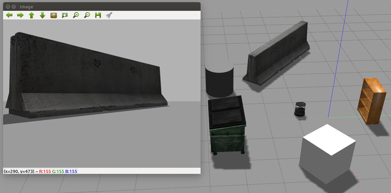
Figure 6.11: The second sequence of the execution of activity nodes

Figure 6.12: The third sequence of the execution of activity nodes
Congratulations! You have completed the activity and at the end, you will have an output which is like figures 6.8, 6.9, and 6.10. By completing this activity successfully, you have been able to implement and work with nodes that let you subscribe to a camera which will show images in the virtual environment. You also learned to rotate a robot on itself that lets you view these images.